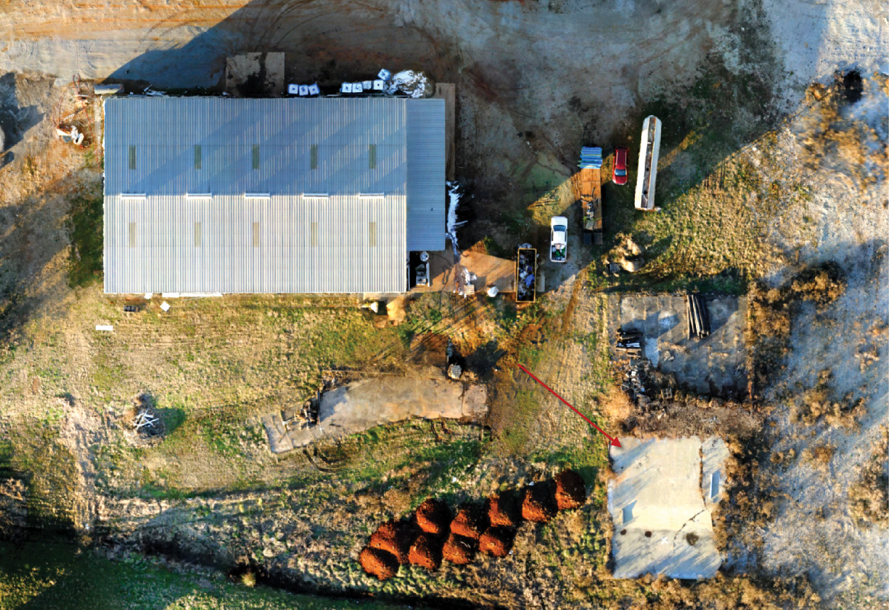
Figure 1: Cement pad used for planar fit analysis (1.5 cm GSD orthophoto from True View cameras).
Drone lidar—the use of compact, lightweight lidars on small unmanned systems—is an active area of research and commercial development. The use of drone lidar has accelerated over the past five years with the opening-up of the air space to commercial drone work. These changes in the regulatory environment, along with advances in lower-cost lidars, primarily developed for the automotive industry, the availability of multi-channel lidars (8-16-32-64-128 channels) and the development of alternatives to mechanical, rotating or oscillating mirror systems, have made drone-based lidar mapping affordable and efficient for many projects that would not be cost-effective with traditional fixed-wing or helicopter surveys. Drone surveys also offer advantages over static scanning in terms of coverage and remote accessibility for many project sites. This latest innovation in lidar is a continuation of the ongoing shift in the commercial lidar industry from “big, heavy, expensive” to “small, light, cheap”.
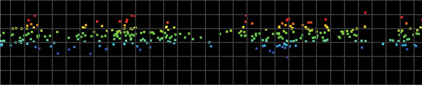
Figure 2: Point-cloud profile before smoothing.
At GeoCue Group we design integrated lidar/camera payloads for use on small commercial drone platforms such as the DJI M600 or the Harris Aerial H6. Our focus is on high-accuracy data collection and processing for base mapping using tightly integrated lidars and mapping cameras in a single sensor. We refer to this as a 3D Imaging Sensor (3DIS) for its combination of high-accuracy elevation data with high-resolution oblique imagery, facilitating the simultaneous generation of a true 3D colorized point cloud and corresponding orthophoto. We focus our research and field testing on how to achieve the highest-accuracy results using relatively low-cost technology, with the goal of making this technology as widely accessible as possible to the survey and mapping community. Under our True View brand, we provide the results of our research and field work as end-to-end hardware and software solutions for researchers and commercial survey and mapping firms.
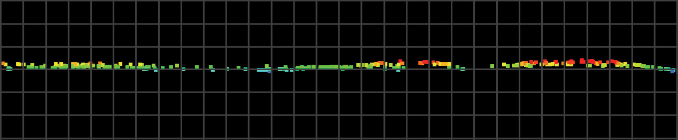
Figure 3: Point-cloud profile after smoothing.
Any preliminary analysis of the drone lidar market will reveal that there are several classes of drone lidar sensors in today’s market with clear price/performance trade-offs. One of the key differentiators in both price and performance is between systems that use an automotive-class lidar (cheaper, but noisier) as opposed to what we consider a survey-grade lidar (more expensive but much less noisy). Another major price differentiator in drone lidar systems is the choice of the inertial navigation system that combines the GNSS position and on-board IMU orientation data to generate a precise trajectory for the lidar and camera. At GeoCue Group we focus on systems intended for high-accuracy data collection for professional survey and mapping projects. We have standardized on the Applanix APX series for direct georeferencing of our sensors.
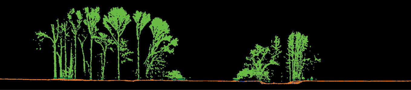
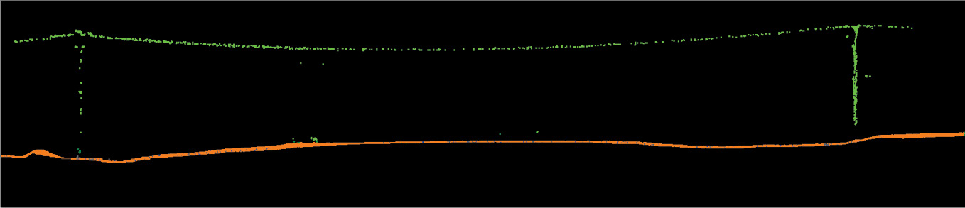
Figure 4: Above and below; Canopy and telephone wires after smoothing/ground classification in True View EVO.
A drawback to using automotive-class lidars, such as the Quanergy M8 Ultra we use in our True View 410, is that such lidars have more shot noise and larger peak-to-peak noise than lidars used in traditional airborne sensors. This noise may be acceptable for inspection and visualization applications or for low-accuracy mapping projects, but is detrimental to any survey or mapping project where accuracy is a key requirement. On a flat, hard surface such as a concrete pad or parking lot, for example the GeoCue test site in Figure 1, there may be upwards of 20 cm peak-to-peak (±10 cm) noise from this class of lidar. This compares to less than 5 cm (±2.5 cm) or even better from a survey-grade system. Many automotive-class lidars are also multi-channel designs with 8 to 128 separate beams in a fan-shaped scan pattern. Compared to the single-channel transceiver designs more common in survey-grade sensors, this increases the sampling rate but at the expense of introducing even more noise in the point cloud. Channel-to-channel calibration requirements for automotive applications are usually not rigorous enough for mapping and can further contribute cross-channel noise to the lower-quality data sets collected with such systems.
 To address this noise challenge, GeoCue has developed smoothing routines in the True View EVO software to reduce the peak-to-peak noise in the point cloud while maintaining the overall accuracy and preserving the detail of fine features and above-ground structures. Typically, this smoothing is done after applying a final debias to the data to correct any residual systematic error in the vertical, but prior to any classification of the point cloud. Debiasing is valid for data sets where the standard deviation of the mean is small compared to the mean. Examples of the results of this smoothing for a Quanergy M8 Ultra (True View 410) point cloud measured over a flat cement pad are shown in Figures 1–3. Figure 1 shows the test pad in a 1.5 cm orthophoto generated from the True View 410 mapping cameras’ imagery using Agisoft’s Metashape. Figures 2 and 3 show a profile of the point cloud data across the pad from west to east before and after smoothing. The graticule in the profile is 5 cm.
By using a planar fit analysis to measure the deviation from the surface of the target, we can quantify the results of the smoothing as shown in Table 1.
By comparing to known field check points, we can measure the vertical RMSE error and any residual Z bias (residual systematic vertical error) of the point cloud both before and after smoothing to verify that the smoothing algorithm has not introduced any additional error into the point cloud. Note that since we debiased the data prior to smoothing, the mean error is zero. The results are shown in Table 2.
Qualitatively we are also able to assess that the planar smoothing has left above-ground features preserved, as can be seen in the profiles of tree canopy and telephone wires in Figure 4.
Smoothing noisy point cloud data from automotive-class drone lidars also improves the results when running a ground classification/bare-earth extraction using an adaptive TIN algorithm. This approach to ground classification is a robust method used in many lidar production software tools, including GeoCue’s True View EVO and LP360 software suites as well as industry-standard tools such as Terrasolid’s TerraScan. The adaptive TIN algorithm uses a spatial angular and distance test to densify a seed surface created from low points in the point cloud. The dense, noisy point-cloud data generated by most automotive-class lidars introduces bias in the selection of low points for the seed surface. The noise in the data also increases the number of false negatives—true ground points left unclassified—due to the larger angles and distances introduced by the greater peak-to-peak distribution. Smoothing the point cloud to reduce this noise on planar surfaces allows the adaptive TIN algorithm to start with a better seed surface and converge faster to a higher-fidelity ground surface. As a result, we have adopted the practice of smoothing point-cloud data prior to ground classification in all cases except where preserving the structure of low ground cover or fine terrain features on the same scale as the lidar point cloud noise envelope is the primary research interest. In such cases smoothing is detrimental to preserving those features and alternative approaches to dealing with the noise from an automotive-class lidar must be considered. Alternatively, the use of a survey-grade drone lidar sensor with inherently lower peak-to-peak noise, such as GeoCue’s True View 615/620, based on the RIEGL miniVUX-2, should be planned.
In summary, there is a range of price/performance options available when selecting a drone lidar sensor. When paired with comparable high-accuracy INS systems, a primary differentiator between these systems is the shot-to-shot noise introduced into the point cloud by multi-channel automotive-class lidars. Using a robust planar smoothing algorithm to reduce the peak-to-peak noise while preserving accuracy and above-ground features is an effective technique for improving the quality of such data sets on most survey and mapping projects.