Editor’s note: For a PDF showing the images, tables and equations click HERE
The first part of the tutorial (lidar basics) reviewed the fundamentals of airborne lidar, also referred to as airborne laser scanning (ALS)1. We concluded that ALS is a multi-sensor system consisting of a navigation component and a scanning lidar device. The Global Navigation Satellite System (GNSS) antenna/receiver and the Inertial Measurement Unit (IMU) provide precise position and attitude information of the carrier platform. The laser scanner itself is again a multi-sensor system consisting of the scanning and the ranging unit. All these components together comprise the complete ALS system, which delivers dense 3D point clouds of the topography, vegetation, buildings, water bodies, and infrastructure, such as power lines and the like. The outstanding features of ALS are (i) high point density of typically 5-30 points/m2 (ppsm), (ii) good height accuracy in the range of 5-10 cm, (iii) planimetric resolution of around 20 cm, and (iv) the capability of penetrating vegetation. The last of these has made airborne lidar the prime technique for capturing countrywide digital elevation data as the basis for national and transnational digital terrain models (DTMs). Next to precise geometry, ALS also provides radiometric information for each laser point, as either signal intensity or even calibrated reflectance. The latter is a measure which reflects properties of the illuminated object only, while the former also depends on mission parameters such as measurement range and incidence angle, as well as system and atmospheric parameters.
ALS sensors as described above have revolutionized large-area elevation data acquisition since around the turn of the century, whereas in earlier years mapping was dominated by aerial photogrammetry based on analogue images. The introduction of digital metric camera systems and the development of efficient photogrammetric computer vision algorithms like Structure-from-Motion (SfM) and Dense Image Matching (DIM), however, has again changed the situation over the last two decades. Especially for the derivation of digital surface models (DSMs), aerial photogrammetry based on multi-view stereo (MVS) nadir and oblique images has proven to be a good choice. As DIM is generally capable of delivering a 3D point for each image pixel, this potentially also increases the spatial resolution of the captured elevation data.
The logical consequence was that manufacturers began to integrate both laser scanners and high-end cameras into comprehensive multi-imaging sensors. This tendency could be observed from both sides, either traditional camera manufacturers integrating laser scanners, or vice versa. Another option for enriching the traditional monochromatic ALS sensors is to operate multiple lasers with different laser wavelengths in a single compound system or to operate multiple monochromatic ALS systems simultaneously on the same aircraft. The first is the manufacturers’ approach, the second that of the system providers. However implemented, the result is a multispectral laser scanner and, therefore, another example of an integrated senor system. The remainder of this tutorial first compares the basics of airborne lidar and multi-view stereo photogrammetry from a conceptual point of view and then introduces integrated lidar-camera sensors available on the market and their features. In addition, existing multispectral lidar solutions are introduced, including a discussion of their advantages, especially for 3D point-cloud classification.
Airborne lidar vs. aerial photogrammetry
In Part I of the tutorial we have already learned that airborne lidar is an active polar measurement system, which uses short laser pulses for time-of-flight-based ranging. This means that an object can be reconstructed in 3D, if it is measured in a single scan strip. One of the specific strengths of lidar is its multi-target capability, enabling the penetration of vegetation to reveal objects below the canopy and to provide data from the ground for deriving a high-resolution DTM. For a complex scene with trees, buildings, a street canyon, and a grass area, this is schematically sketched in Figure 1(a).
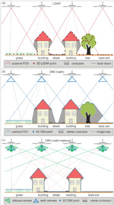
Figure 1: Schematic drawing of data acquisition based on (a) airborne lidar, (b) DIM with nadir images, and (c) DIM with nadir/oblique images.
Driven by advances in digital camera technology and photogrammetric computer vision algorithms, modern image-based 3D surface reconstruction techniques also provide a high level of precision and robustness. Starting from a set of images and their corresponding camera parameters (i.e. interior and exterior orientation), MVS algorithms first compute so-called disparity maps, applying suitable stereo matching algorithms such as semi-global matching. As a result, stereo correspondences between pixels across image pairs are established, enabling the derivation of dense 3D point clouds via forward intersection. In addition, matching each image against multiple overlapping images generates redundant depth observations. Thus, each single pixel of an image block provides one or more corresponding 3D coordinate triplets. The resulting dense point cloud can subsequently be filtered during DSM generation. If suitable redundancy is available from multiple views, state-of-the-art algorithms can reconstruct surface geometry at a resolution that corresponds to the resolution of the available imagery. Since the size of an image pixel on the ground (ground sampling distance, GSD) is usually smaller than the footprint diameter of an airborne lidar system, DIM potentially delivers a higher point density compared to lidar. As objects can only be reconstructed from images if they are visible in at least two images, however, (stereo) occlusion is generally higher in the case of image-based 3D surface reconstruction. Figure 1(b) illustrates this for nadir images, which is the standard case in aerial photogrammetry.
To mitigate stereo occlusion and to enable reconstruction of vertical façades in densely populated city areas, modern image-based sensor systems use oblique cameras in addition to standard nadir cameras. A well-established, multi-camera configuration consists of one nadir camera and four oblique cameras (front, back, left, right) tilted by 45°. Figure 1(c) demonstrates the significant reduction of the stereo occlusion using oblique and nadir images for a schematic scene with two buildings. It is noteworthy here that the joint orientation of nadir and oblique images is more challenging than the nadir-only case due to pronounced scale differences in the oblique images.
To round up this section with theoretical considerations, Table 1 gives an overview of the features and characteristics of airborne lidar and DIM.
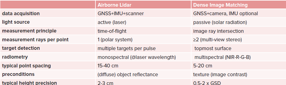
Table 1: Features and characteristics of lidar and DIM.
Lidar-camera integrations
As stated in the introduction, airborne sensors for acquisition of 3D elevation data nowadays combine laser scanners and camera systems. Table 2 provides a selection of state-of-the-art sensor systems from four manufacturers – Hexagon/Leica Geosystems, RIEGL Laser Measurement Systems, Vexcel Imaging, and Teledyne Geospatial.
All the sensors in Table 2 use an Nd:Yag laser (neodymium-doped yttrium aluminum garnet) at a wavelength of around 1064 nm with a pulse repetition rate (PRR) of 2 MHz or more. They all provide the possibility to integrate one or more digital aerial cameras—either RGB, NIR, or compound RGBN. Most of the systems have the cameras tightly integrated and the scan pattern of the lidar unit is adjusted to match the footprint of aerial images. Figure 2 shows the scan-image layout for selected sensors.
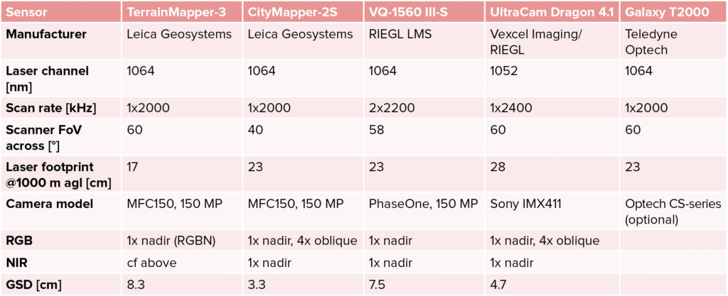
Table 2: Setup and specifications of selected integrated lidar-camera sensors; laser footprint and image GSD are reported for a flying altitude of 1000 m agl.
The Leica TerrainMapper-3 integrates a lidar unit and a 150 MP RGBN frame camera. The system features a narrow laser beam with footprint diameter of 17 cm when flying at an altitude of 1000 m above ground level (agl). At this altitude, the image GSD measures 8.3 cm. The scan pattern, produced by a dual-wedge Risley prism, is circular and the diameter covers the full 60° across-FoV of the RGBN images (Figure 2(d)).
RIEGL’s VQ-1560 III-S is a dual-channel laser system. Each of the two lasers fires with a PRR of 2.4 MHz. Both lasers are deflected by a single four-sided polygonal mirror wheel and form an X-shaped scan pattern on the ground. The two scan lines are inclined by ±14° to optimize the point distribution on the ground and to allow nadir and sideward but also slightly forward and backward looks (Figure 2(c)). The lateral FOV of 58° matches the size of the integrated PhaseOne 150 MP RGB camera.
Both the Leica TerrainMapper-3 and the RIEGL VQ-1560 III-S use the integrated cameras primarily for colorization of the 3D laser point cloud, which enhances the interpretability of the laser data. The images can also be used for classical aerial photogrammetry, however, to derive digital orthophotos. However, as both systems only use nadir cameras, the independent derivation of a 3D point cloud via MVS and DIM suffers from stereo occlusion as explained earlier and as can be seen in Figure 1(b). To complement the laser point cloud with a complete and gapless image-based point cloud including points on façades, oblique images are needed.
The Leica CityMapper-2 sensor system is optimized for urban 3D data acquisition and combines a 2 MHz lidar unit with six aerial MFC150 cameras. Two cameras (RGB, NIR) face downwards in the nadir direction and four RGB cameras point obliquely, forward, backward, left, and right. The setup of the lidar unit corresponds to that of the Leica TerrainMapper-3, and, for the Leica CityMapper-2S system shown, the circular scan pattern matches the base area of the NIR nadir image with an across-FOV of 40°. As can be seen in Figure 2(a), the footprint of the RGB image is smaller compared to the NIR image by a factor of 1.6. The setup with nadir and oblique images enables the independent derivation of a comprehensive 3D point cloud from images and scans, respectively. This redundancy can be used to fill eventual gaps in one of the data sources. One disadvantage of the circular scan pattern is the lack of nadir views, which are advantageous for object detection in narrow street canyons. The constant off-nadir angle of the conical scanning mechanism, on the other hand, enables oblique laser beam vectors in all wind directions. Together with a suitable side overlap of 50°, this enables the capture of buildings from all sides in both scans and images.
The basis of Vexcel Imaging’s UltraCam Dragon 4.1 sensor system is the well-proven UltraCam camera family. The system consists of two equally sized nadir cameras (RGB, NIR) and four oblique cameras. The system depicted in Figure 2(b) uses a 50 mm lens for the nadir camera with a FOV of 36.8° across track and 27.9° along track. The system is complemented with a RIEGL VQ-680 OEM laser scanner operating at a PRR of 2.4 MHz. The scanner uses a five-sided polygonal mirror wheel, where each side is slightly tilted in relation to the next side. The first mirror face deflects the laser beams vertically down and enables nadir looks in the middle of the flight strips. The other four mirror faces are manufactured to deflect the beams 20° and 40° forward and backward, respectively (Figure 2(b)). With a lateral scanner FOV of 60°, a full rotation of the mirror wheel results in five scan lines, which fully cover and even extend the nadir images of the UltraCam. Thus, this scan pattern combines the advantages of vertical and oblique scanning, which optimally complements the nadir-oblique camera setting of the system. As in the case of the Leica CityMapper-2, the setup provides an optimal configuration for colorizing the laser point cloud and allows for mutual gap-filling of the lidar- and image-derived point clouds. Such comprehensive data is the ideal basis for city modeling, 3D mesh generation, solar potential studies, analysis of urban green space and the like.
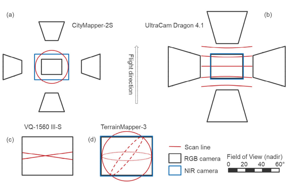
Figure 2: Schematic drawing of the scan and image setup of selected integrated sensor systems.
Figure 3 shows an example of an urban scene captured with an integrated lidar-camera system. The scene in downtown Munich (Germany) was captured with the Leica CityMapper-2. The lidar point cloud is RGB-colored based on the nadir and oblique MFC150 images.
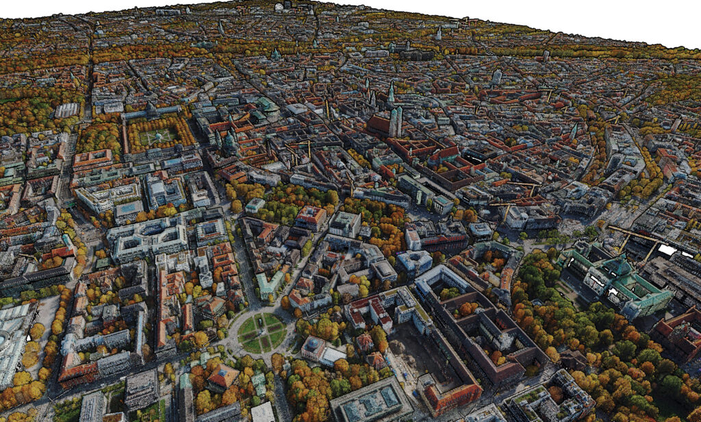
Figure 3: RGB-colored 3D point cloud of the city center of Munich, Germany. Data acquired with a Leica CityMapper-2.
Figure 4 shows another example of an urban scene (Graz, Austria) acquired with the Vexcel Imaging UltraCam Dragon 4.1. The left-hand shows the RGB-colored point cloud derived from the nadir and oblique images via DIM and the lidar point cloud of the VQ-680-OEM laser scanner colored by intensity. All scenes shown in Figures 3 and 4 feature high completeness including points on façades and in street canyons.
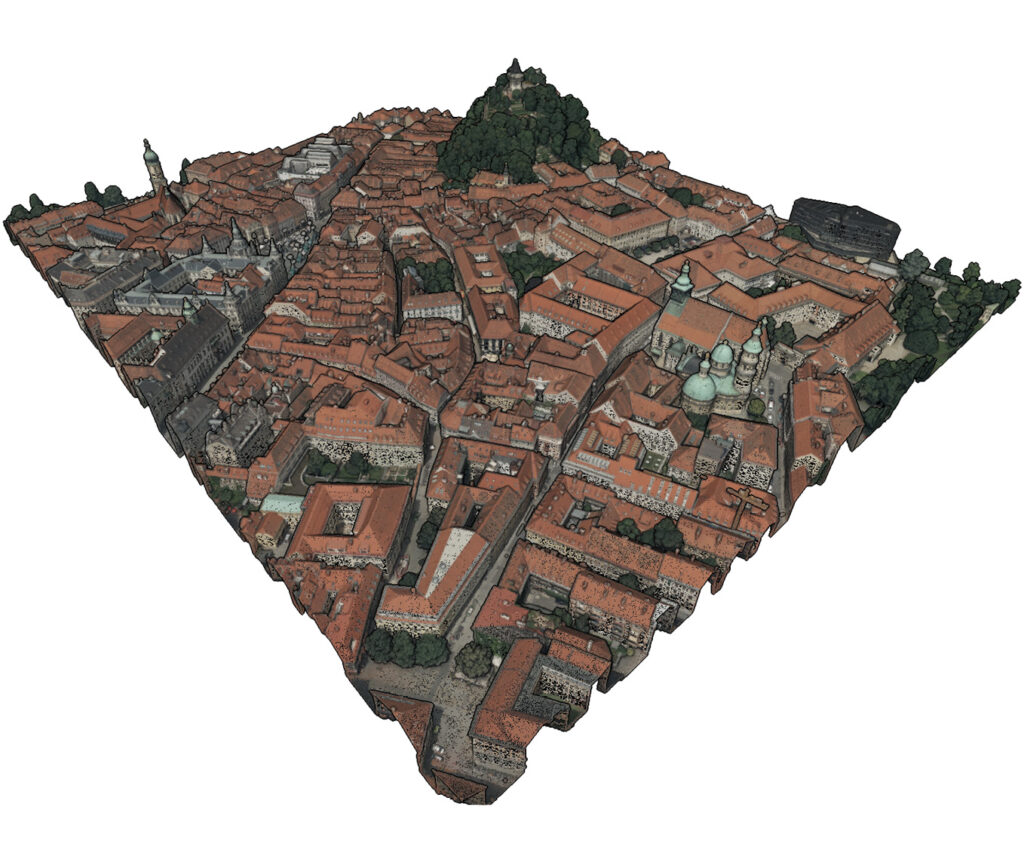
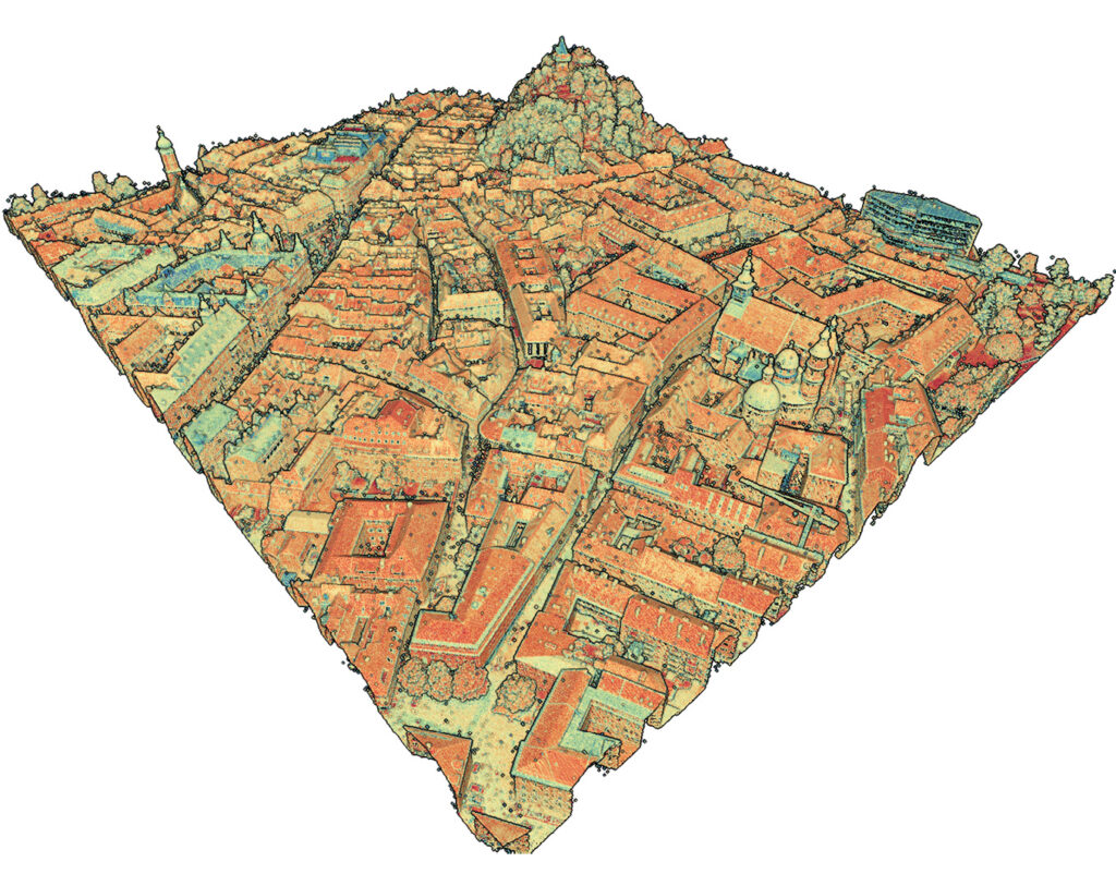
Figure 4: Urban scene in Graz, Austria acquired with the Vexcel Imaging UltraCam Dragon 4.1 — RGB-colored point cloud derived from the nadir and oblique images via DIM (top) and lidar point cloud of the VQ-680-OEM laser scanner colored by intensity (bottom).
Multispectral lidar
Another option to enrich monochromatic airborne lidar systems is to use multiple laser wavelengths and thus create a multispectral lidar instrument. While precise geometry and vegetation penetration are the most prominent features of airborne lidar, practically all lidar sensors also provide intensity information. Once the raw lidar amplitude/intensity readings are corrected for the dominant range and incidence angle effects (see details in Part I of this tutorial), it is possible to derive a radiometrically calibrated reflectance attribute for each point. Such information is beneficial for semantic labeling of the lidar point cloud, as we will see later in this section.
Constructing a multispectral airborne lidar sensor involves careful planning of the setup with respect to both signal detection (range, signal intensity, pulse shape…) and beam steering. Ideally, a multispectral instrument would rely on a super-continuum laser, also referred to as a white laser, and send out the entire spectrum in a single laser pulse. This means that all wavelengths of the pulse propagate at the same time, in the same direction and with the same beam characteristics (pulse length, beam divergence). On the signal detection side, this means that a wavelength-dependent beam splitter has to split the incoming echo pulse and steer it to individual detectors, which are sensitive to the respective wavelengths. While such concepts are commonly used in microscopy and spectroscopy, in the mapping environment super-continuum lasers have been applied successfully only in terrestrial, close-range applications but not for airborne lidar.
For enabling multispectral information in airborne lidar, multiple monochromatic lasers and corresponding receivers are used. The individual laser pulses are commonly deflected via a single scanning device—a mirror, polygonal wheel, or Risley prism—but typically not at the same time and not in the same direction. In addition, the pulse length and the beam divergence may differ between the individual lasers, mainly because of eye safety considerations, especially when using visible green lasers as part of a multispectral instrument. While concurrent and coaxial pulse emissions of the individual monochromatic lasers would be desirable, the implementation is technically demanding. In practice, multispectral instruments therefore deliver individual 3D point clouds for the individual lidar units. In post-processing, it is then possible to fuse the individual monochromatic point clouds to a joint multispectral point cloud by attaching the missing radiometric information from neighboring points of the remaining channels based on spatial neighborhood queries. A potential problem in such a setup is scan shadows, which may differ from one wavelength laser channel to another due to different viewing geometry. Two instruments implementing this strategy are the Teledyne Optech Titan and the RIEGL VQ-1560 DW. The basic specifications of both instruments are summarized in Table 3.
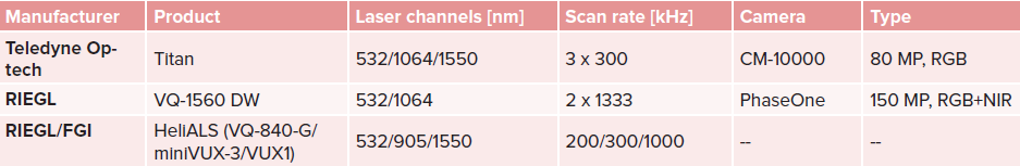
Table 3: Examples of multispectral airborne lidar sensor systems.
The RIEGL VQ-1560 DW (DW = dual wavelength) is a variant of the VQ-1560 III-S sensor described in the previous section. It provides a NIR and a green laser operating at wavelengths of 1064 nm and 532 nm respectively. The X-shaped scan pattern is the same as depicted in Figure 2(c). The only difference is that one of the two NIR channels is replaced by a green channel. In addition to the two laser channels, the device also has two nadir cameras (RGB, NIR), making it an integrated system in two respects. Using the blue and the red channels from the passive imagery, a 3D point cloud with four spectral bands can be derived. In this scenario, the entire geometry would come from the lidar acquisition and the spectral content would be derived either directly from the laser measurements (NIR, green) or from the images (blue, red).
In addition to the two 532 and 1064 nm bands of the VQ-1560 DW, the Teledyne Optech Titan instrument has an additional SWIR channel at a wavelength of 1550 nm. The individual laser pulses are deflected via a single oscillating mirror. The scan planes are vertical for one channel and 7° forward or backward, respectively, for the other two channels. The three monochromatic channels allow the creation of a combined 3D point cloud, where each point features three laser-derived intensities (532/1064/1550 nm), which can be visualized as a false-color composite. An example is shown in Figure 5. Researchers have used Teledyne Optech Titan data for various applications, most importantly for improved point cloud classification especially in forested environments, where the multispectral content also helps to identify individual tree species from both the geometric and radiometric content of the data.
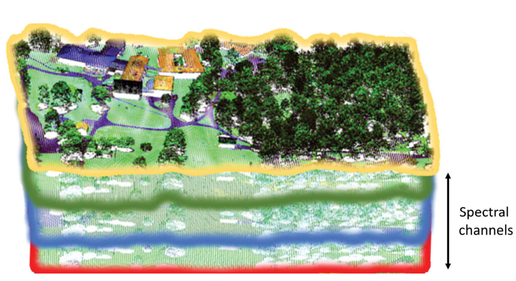
Figure 5: 3D multispectral point composed of Teledyne Optech’s three laser channels, false color composite: blue (532 nm), green (1064nm), red (1550 nm).
Following the initial hype after 2015, when the instruments mentioned above were introduced to the market, the interest in multispectral lidar decreased in the following years. One of the reasons was that the Teledyne Optech Titan sensor is no longer available. Today, however, the scientific community demonstrates an increasing interest, especially as compact sensors are now available, which opens the door for integrating multiple monochromatic sensors on a joint airborne platform (for example, a helicopter). The forestry industry is also the driving force here, due to the strong demand for improved biomass estimates. In the context of climate transition, it is of the utmost importance to monitor the development of the Earth’s forests, as wood plays a key role as a building and heating material. Classification of tree species is facilitated by the availability of both precise geometry and radiometry, as certain tree species can be detected based on their geometric shape and a further distinction is possible based on reflectivity or reflectance. Table 3 also lists a system developed by the Finnish Geodetic Institute (FGI), consisting of three compact RIEGL laser scanners with wavelengths of 532 nm (VQ-840-G, green), 905 nm (miniVUX-3, NIR), and 1550 nm (VUX-1HA, SWIR). Similar systems are also feasible for manned aircraft by combining, for example, a topobathymetric sensor (532/1064 nm) with a second scanner operating at 1550 nm.
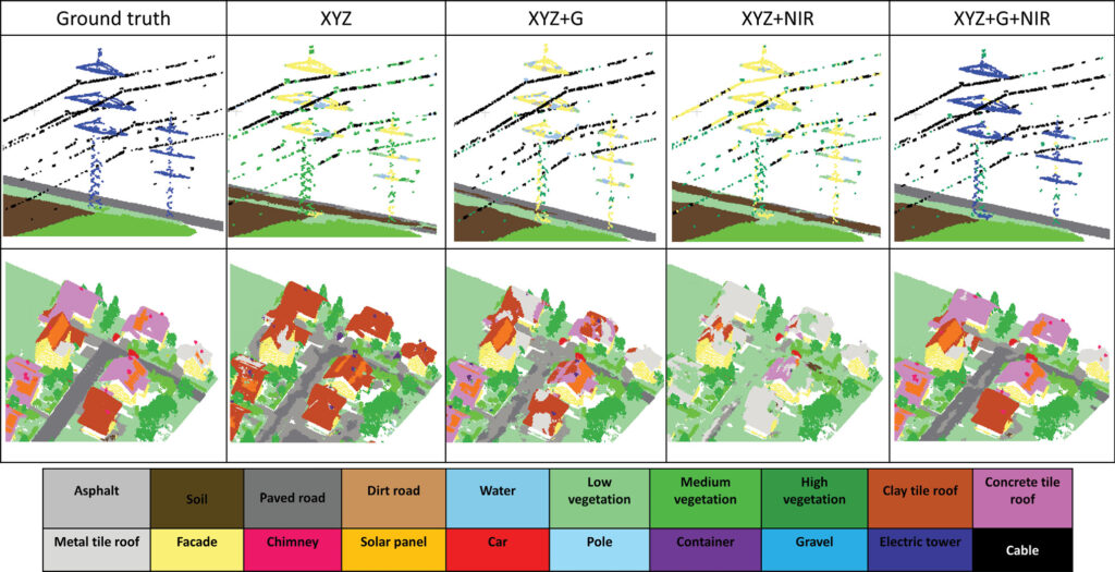
Figure 6: Labeled 3D multispectral point cloud of a high-voltage pylon scene captured with the RIEGL VQ-1560 DW sensor: manually labeled reference (ground truth) and different classification results, based on deep learning, using geometry only (XYZ), geometry + single-band reflectance (XYZ+G, XYZ+NIR), and geometry + multispectral reflectance (XYZ+G+NIR).
The examples shown in Figures 5 and 6 highlight the benefits of multispectral airborne lidar for improved semantic labeling. The scene around a high-voltage pylon recorded with the RIEGL VQ-1560 DW dual wavelength sensor (Loosdorf, Austria) cannot be correctly classified based on either the 3D geometry (XYZ) alone or with the inclusion of single-band radiometry (XYZ+G, XYZ+NIR). In contrast, the use of the spectral information of both green and NIR laser channels together with the geometry (XYZ+G+NIR) provides an almost perfect separation of cables, pole, ground, paved road, low and medium vegetation. This result was achieved automatically with deep learning (KPConv). Figure 7 depicts an urban scene with vegetation patches captured with the HeliALS system in Espoonlahti, Finland. The 3D multispectral point cloud is shown as a false color composite (left) and colored by class labels (right). Again, KPConv-based semantic segmentation provides a very good separation of the dense points into the detailed categories façade, roof, asphalt, tree, grass, gravel, and car.
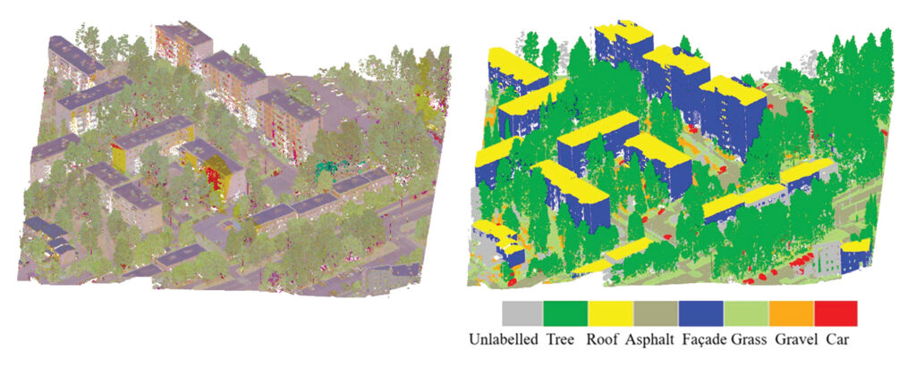
Figure 7: 3D multispectral point cloud (left) with class labels (right) of a scene in Espoonlahti, Finland. Data acquired with the HeliALS sensor system.
Conclusions
While monochromatic airborne lidar is a proven technology for the acquisition of nationwide terrain elevation data, the combination of laser scanners and digital cameras has opened new applications. Colored point clouds are much easier to interpret for both humans (visualization) and machines (classification). In addition, the combination of lidar and dense image matching creates denser point clouds than are achievable with a single sensor alone. In particular, integrated sensors equipped with nadir and oblique cameras can provide point clouds of façades and narrow street canyons based on both images and laser scans. The redundancy can be used to fill gaps in each other’s data sets. The scan mechanism of airborne lidar sensors, used together with advanced nadir/oblique camera systems, is usually optimized for omnidirectional laser beam deflection. This can be accomplished with either conical (Palmer) scanning or polygonal mirror wheels with differently inclined mirror surfaces providing parallel scan lines with sideward, forward and backward views. Another possible improvement to standard monochromatic lidar is the inclusion of multiple laser wavelengths in a single sensor system. Such multispectral systems offer great potential for point cloud classification and enable much finer class granularity with potential applications in urban mapping, land cover mapping, tree species classification, biomass estimation, and many more. Dual-wavelength multispectral lidar sensors using green and NIR laser radiation are the basis for airborne laser bathymetry, the topic of Part III of this tutorial, which will appear in the next issue of LIDAR Magazine.
Further reading
Glira, P., N. Pfeifer and G. Mandlburger, 2019. Hybrid orientation of airborne lidar point clouds and aerial images, ISPRS Ann. Photogramm. Remote Sens. Spatial Inf. Sci., IV-2/W5: 567–574. https://doi.org/10.5194/isprs-annals-IV-2-W5-567-2019.
Hakula,A., L. Ruoppa, M. Lehtomäki, X. Yu, A. Kukko, H. Kaartinen, J. Taher, L. Matikainen, E. Hyyppä, V. Luoma, M. Holopainen, V. Kankare and J. Hyyppä, 2023. Individual tree segmentation and species classification using high-density close-range multispectral laser scanning data, ISPRS Open Journal of Photogrammetry and Remote Sensing, 9: 100039, August 2023. https://doi.org/10.1016/j.ophoto.2023.100039.
Takhtkeshha, N., G. Mandlburger, F. Remondino and J. Hyppä, 2024. Multispectral light detection and ranging technology and applications: A review. Sensors, 24(5): Article 1669. https://doi.org/10.3390/s24051669.
Toschi, I., E.M. Farella, M. Welponer and F. Remondino, 2021, Quality-based registration refinement of airborne LiDAR and photogrammetric point clouds, ISPRS Journal of Photogrammetry and Remote Sensing, 172: 160-170.
- 1 Mandlburger G., 2024. Airborne lidar: a tutorial for 2025. Part I: Lidar basics, LIDAR Magazine, 14(4): 26-31, December 2024.