The geospatial industry is fortunate to have the American Society for Photogrammetry and Remote Sensing (ASPRS) to safeguard and advance industry best practices and proper conduct. The ASPRS Positional Accuracy Standards for Digital Geospatial Data of 2014 set out the first accuracy standards developed for digital mapping practices and provided the beacon for this guidance.
The ASPRS Positional Accuracy Standards for Digital Geospatial Data, Edition 2 was approved by the ASPRS Board of Directors on August 23, 2023. This edition was developed through observations and feedback over the last seven years. It became apparent that a new edition of the standards was needed to incorporate recommendations, correct outdated guidelines, and address quickly evolving sensors, technologies, and industry practices.
This article highlights the main features of the standards and notes the changes introduced in the second edition. It will also help readers understand the new standards and how they apply to everyday mapping activities.
The second edition was developed by community consensus, with specialists from private companies, public agencies, and academia contributing to its development. For the first time, four state departments of transportation contributed to these standards. This paradigm of participation was created to expand the standards to the wider community of mapping, remote sensing, and engineering practices.
Motivation behind the new ASPRS accuracy standards
- Legacy map accuracy standards, such as the U.S. National Map Accuracy Standards (NMAS) of 1947 and ASPRS 1990 standards, have become outdated.
- Many of the data acquisition and mapping technologies on which these standards were based are no longer used.
- Recent advances in mapping technologies can produce better quality and higher accuracy geospatial products and maps.
- Legacy map accuracy standards were designed with only plotted or drawn maps to represent geospatial data.
- Within the past two decades, as the industry transitioned between hardcopy and softcopy mapping environments, most standard measures for relating ground sample distance (GSD) and map scale to the final mapping accuracy were inherited from photogrammetric practices using scanned film.
- New mapping processes and methodologies have become much more sophisticated with advances in technology and in our knowledge of mapping processes and mathematical modeling.
- Mapping accuracy can no longer be associated with camera geometry and flying altitude alone (focal length, xp, yp, B/H ratio, etc.).
- Elevation products from the new technologies and active sensors—such as lidar, UAS, and IFSAR—are not covered in the legacy mapping standards. New accuracy standards are needed to address elevation products derived from these technologies.
- Today’s mapping accuracy is influenced by many factors, such as:
- Quality of camera calibration parameters
- Quality and size of a charged coupled device (CCD) used in the digital camera CCD array
- Amount of imagery overlap
- Quality of parallax determination or photo measurements
- Quality of GPS signal
- Quality and density of ground controls
- Quality of the aerial triangulation solution
- Capability of the processing software to handle GPS drift and shift
- Capability of the processing software to handle camera self-calibration
- The digital terrain model used to produce orthoimagery.
These factors can vary widely from project to project, depending on the sensor used and specific methodology. For these reasons, existing accuracy measures based on map scale, film scale, GSD, c-factor, and scanning resolution no longer apply to current geospatial mapping practices.
New standards for a new era
While old standards guided the initial practices of mapmaking that was based on paper map media and film cameras, new digital sensor technologies such as lidar, digital cameras, and geospatial products and practices challenged these standards. Highlights of the new standards include:
- Sensor-agnostic, data-driven
- Designed for today’s digital sensors and mapping practices
- Positional accuracy measure that is based on ground measurement units, not map units
- Positional accuracy thresholds that are independent of published GSD, map scale or contour interval
- It is all metric!
- Unlimited horizontal and vertical accuracy classes to support any sensor technology
- Based on root mean square error (RMSE) alone as an accuracy indicator
- Provides additional accuracy measures such as:
- Aerial triangulation accuracy
- Ground control accuracy
- Orthoimagery seam lines accuracy
- Lidar relative swath-to-swath accuracy
- Independent checkpoint accuracy
- Provides recommended minimum nominal pulse density (NPD) for lidar data
- Provides a measure for horizontal accuracy for elevation data
- Provides guidelines on number and spatial distribution of checkpoints based on project area
- Introduces the new 3D accuracy measure
- Five addenda on guidelines and best practices for various mapping techniques
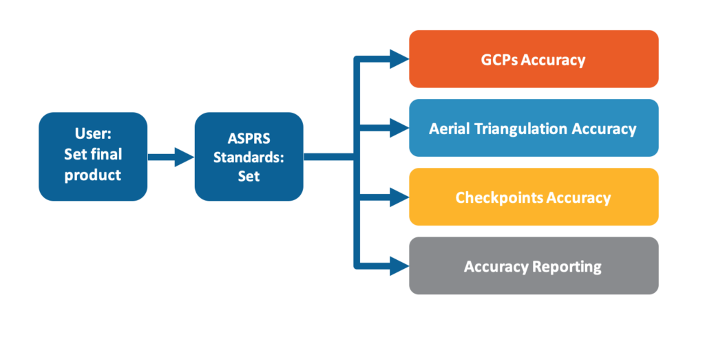
- Ease of use and application. New to the industry, the standards simplify’ for the user the complicated task of requirements for the intermediate processes that are involved in producing final products. An example is that users can specify the required product accuracy and the standards will set all requirements for aerial triangulation accuracy, ground control point accuracy, checkpoint accuracy, etc. The figure below illustrates this characteristic of the new standards.
For very small projects where the use of 30 checkpoints is not feasible, report the accuracy as suggested in section 7.15 of the standards.
Introducing Edition 2
In 2022, ASPRS established a formal Positional Accuracy Standards Working Group under its Standards Committee to evaluate user comments and consider technology advancements to implement appropriate changes to the standards. Based on the feedback received from the industry and the advances the industry has witnessed in sensor technologies and best practices, the following important changes were introduced in Edition 2:
Change #1: Relaxed accuracy requirement for ground control and checkpoints
As demand for geospatial products with higher accuracy increases, the accuracy requirements for the surveyed ground control and checkpoints have increased accordingly. According to Edition 1 of the standards, the accuracy of ground controls required for photogrammetric work needs to be four times better than the produced products, and checkpoints need to be three times better than the assessed product.
Advances in today’s sensor technologies, processing software and algorithms, and processing methodology are enabling us to produce more accurate products. Therefore, we no longer need the three or four times “safety factor” to ensure the desired accuracy of the delivered products. In addition, imposing such restrictive requirements for the ground control and checkpoint surveys imposed a burden on field surveying practices when using Global Navigation Satellite System (GNSS) techniques. Real-time kinematic (RTK)-based surveys also became ineligible to support some high-accuracy products, like the U.S. Geological Survey’s Quality Level 0 lidar.
Change #2: Eliminated references to 95% confidence level as accuracy measure
The 95% confidence measure of accuracy for geospatial data was introduced in the National Standard for Spatial Data Accuracy (NSSDA), published by the Federal Geographic Data Committee in 1998. This measure was carried forward in the ASPRS Guidelines for Vertical Accuracy Reporting for Lidar Data published in 2004, as well as in Edition 1 of these standards.
Although Edition 1 endorses the use of RMSE as the main accuracy measure, it also references the 95% confidence level throughout. Experience has shown that reporting two quantities that represent the same accuracy at different confidence levels creates confusion for users and data producers alike. Users cannot compute accuracy at the 95% confidence level without computing RMSE first, therefore there is no need for a second accuracy that is derived from the first accuracy. The RMSE is a straightforward accuracy measure that is easy to understand and compute.
Change #3: Required inclusion of survey checkpoint accuracy when computing accuracy of final product
Since checkpoints and control points are no longer needed to meet the accuracy of three or four times the intended product and demands for high-accuracy products are on the rise, errors in the surveyed checkpoints used to assess final product accuracy, although small, can no longer be neglected. As product accuracy increases, the impact of error in checkpoints on the computed product accuracy increases. When final products are used for further measurements, calculations, or decision-making, the reliability of these subsequent measurements can be better estimated if the uncertainty associated with the checkpoints or control points is factored in.
Change #4: Removed pass/fail requirement for vegetated vertical accuracy for lidar data
Data producers and data users reported that they were challenged in situations where Non-Vegetated Vertical Accuracy (NVA) is well within contract specifications, but Vegetated Vertical Accuracy (VVA) is not. Since VVA is influenced by factors that fall outside the lidar system accuracy, it is fair to all parties involved in a contract to base the data acceptance or rejection decision for the overall project on the quality of the tested NVA.
In most cases, the VVA assessment is compromised and the quality of lidar-derived surface under trees is affected for the following reasons:
1) Vegetation blocks the lidar pulse from reaching the ground, resulting in less-than-perfect density of the point cloud representing the terrain.
2) The compromised density of lidar points reaching the ground under trees results in poor modeling of the terrain where the checkpoints are located.
3) The performance of algorithms used to separate below-ground and above-ground points in vegetated areas.
4) The quality of GNSS-based surveying techniques in vegetated areas is compromised due to restricted satellite visibility and multipath issues.
Edition 2 calls for the VVA to be evaluated and reported as it is found, but it should not be used as a criterion for rejection or acceptance.
Change #5: Increased minimum number of checkpoints required for product accuracy assessment from 20 to 30
In Edition 1, a minimum of 20 checkpoints was required for testing positional accuracy of a final mapping product. This minimum was not based on rigorous science or statistical theory, but was a holdover from NMAS of 1947, published by the U.S. Bureau of the Budget.
In Edition 2, a better scientific approach is introduced based on a well-respected theorem in statistics, the central limit theorem. According to the central limit theorem, regardless of the distribution of the population, if the sample size is sufficiently large (n ≥ 30), then the sample mean is approximately normally distributed, and the normal probability model can be used to quantify uncertainty when making inferences about a population based on the sample mean. Therefore, in Edition 2 a product accuracy assessment must have a minimum number of 30 checkpoints to be considered fully compliant.
Change #6: Limited maximum number of checkpoints for large projects to 120
According to Edition 1 guidelines, large projects require hundreds, sometimes thousands of checkpoints to assess product accuracy. These numbers have proved to be unrealistic for the industry, as they inflate project budgets and, in some cases, hinder project executions—especially for projects in remote or difficult-to-access areas.
Since Edition 2 recognizes the central limit theorem as the basis for statistical testing, there is insufficient evidence to support the need to increase the number of checkpoints indefinitely as the project area increases. The new maximum number of 120 checkpoints is equal to four times the number cited by the central limit theorem, and that should provide a statistically valid sample.
Change #7: Introduced new accuracy term: “three-dimensional positional accuracy”
Three-dimensional models and digital twins are gaining acceptance in many engineering and planning applications. Many future geospatial data sets will be in true 3D form. Therefore, a method of assessing positional accuracy of a point or feature within a 3D model is needed to support future innovation and product specifications. 3D models require 3D accuracy, rather than separate horizontal and vertical accuracies. Edition 2 endorses the use of the following three terms:
- Horizontal positional accuracy
- Vertical positional accuracy
- 3D positional accuracy
Change #8: Addenda on best practices and guidelines
With geospatial mapping practices and technologies evolving quickly, users need guidelines on how to keep up. In response, Edition 2 introduced the following five addenda:
Addendum I: General Best Practices and Guidelines
Addendum II: Best Practices and Guidelines for Field Surveying of Ground Control and Checkpoints
Addendum III: Best Practices and Guidelines for Mapping with Photogrammetry
Addendum IV: Best Practices and Guidelines for Mapping with Lidar
Addendum V: Best Practices and Guidelines for Mapping with UAS
Understanding Edition 2 of ASPRS Positional Accuracy Standards for Digital Geospatial Data
“Edition 2 was developed through observations and feedback over the last seven years. It became apparent that a new edition of the standards was needed to incorporate recommendations, correct outdated guidelines, and to address quickly evolving sensors, technologies, and industry practices.”
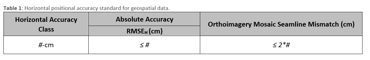
Horizontal positional accuracy standard for geospatial data
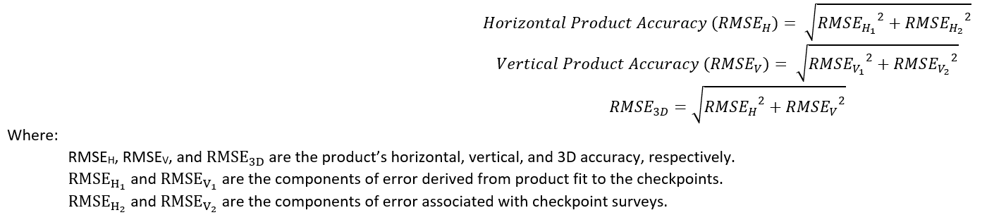
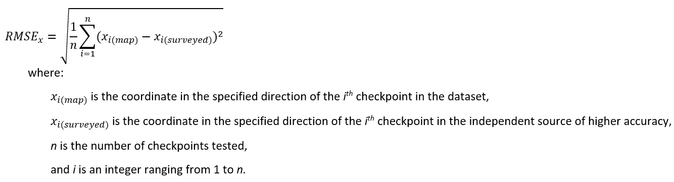
The standards specify horizontal accuracy classes as they relate to digital orthoimagery, digital planimetric data, scaled planimetric maps, and elevation data in terms of RMSEH, which is the combined linear error along a horizontal plane in the radial direction. RMSEH is derived from RMSEX and RMSEY according to the following formula:
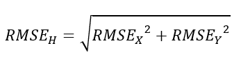
In the case of digital orthoimagery mosaics, an additional criterion for the allowable mismatch at seamlines of ≤ 2* RMSEH is specified in Table 1. The term RMSEH should be computed using both and error components, as will be illustrated in the next sections.
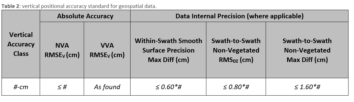
Vertical positional accuracy standard for elevation data
Vertical accuracy is to be expressed as RMSEV in both vegetated and non-vegetated terrain. Vertical accuracy classes are defined by the associated RMSEV specified for the product. The term RMSEV should be computed using both and error components, as will be illustrated in the next sections. While the NVA must meet accuracy thresholds listed in Table 2, the VVA does not pass or fail and needs only to be tested and reported as found. If the NVA meets user specifications, the VVA should be accepted at the reported accuracy level. Table 2 shows the vertical accuracy class specifications for digital elevation data, including Data Internal Precision requirements where applicable, such as in lidar.
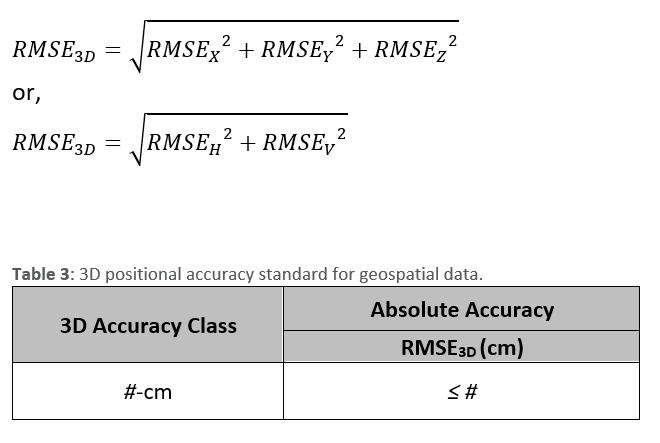
3D positional accuracy standard for geospatial data
3D positional accuracy can be computed for any type of geospatial data, as long as the horizontal and vertical positional accuracy are assessed and reported. It is especially useful in assessing accuracy for colorized point clouds and digital twins. Table 3 defines the 3D accuracy standard for any 3D digital data as a combination of horizontal and vertical radial error. RMSE3D is derived from the horizontal and vertical components of error according to the following formula:
Horizontal accuracy of elevation data
The standards outline horizontal accuracy testing requirements for elevation data created from stereo photogrammetry and lidar. For other technologies, appropriate horizontal accuracies for elevation data should be negotiated between the data producer and the client, with specific accuracy thresholds and methods based on the technology used and the project design. Horizontal accuracy for elevation data is determined using one of the following approaches:
- Photogrammetric elevation data: For elevation data derived using stereo photogrammetry, apply the same horizontal accuracy class that would be used for planimetric data or digital orthoimagery produced from the same source, based on the same photogrammetric adjustment.
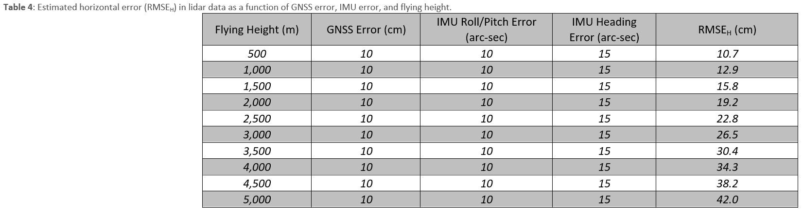
- Lidar elevation data: The standards provide the following equation to estimate the horizontal accuracy for a lidar-derived dataset (RMSEH), based on the main errors introduced by the positional accuracy of the GNSS; roll, pitch, and heading accuracy of the inertial measurement unit (IMU); and the flying height:
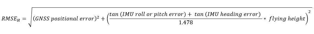
Using the above equation, the horizontal accuracy of lidar data acquired from different flying altitudes is listed in Table 4.
Accuracy requirements for aerial triangulation and IMU-based sensor orientation
The quality and accuracy of the aerial triangulation, if performed, and/or the GNSS/IMU-based direct georeferencing play key roles in determining the final accuracy of imagery-derived mapping products.
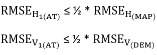
-For aerial triangulation designed for digital planimetric data (orthoimagery and/or map) only:
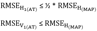
-For aerial triangulation designed for projects that include elevation or 3D products, in addition to digital planimetric data (orthoimagery and/or map):
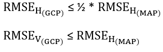
Accuracy requirements for ground control used for aerial triangulation
The accuracy of the ground control points should be twice the target accuracy of the final products, according to the following two categories:
-Ground control for aerial triangulation designed for digital planimetric data (orthoimagery and/or map) only:
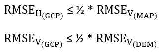
-Ground control for aerial triangulation designed for projects that include elevation or 3D products, in addition to digital planimetric data (orthoimagery and/or map):
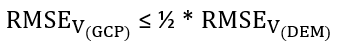
Accuracy requirements for ground control used for lidar
The accuracy of the ground control points used for lidar calibration and boresighting should be twice the target accuracy of the final products. Similarly, ground checkpoints used to assess lidar data accuracy should be twice the target accuracy of the final products.
Similar guidelines can be followed for other digital data acquisition technologies, such as IfSAR.
Positional accuracy assessment of geospatial data products
Knowing the positional accuracy of a geospatial product is important, as it plays a major role in determining the applicability of the data for an intended purpose. Mislabeled or poorly reported positional accuracy can have catastrophic consequences. Therefore, the geospatial data exchanged among users should be accompanied by metadata clearly stating its positional accuracy.
Number and distribution of checkpoints for horizontal accuracy and NVA assessment
According to Edition 2, a minimum of 30 checkpoints is needed to assess the horizontal and non-vegetated vertical accuracy of a dataset. A large project, or more than 1000 square kilometers, will need more checkpoints. Table 5 lists the recommended number of checkpoints according to the project size.
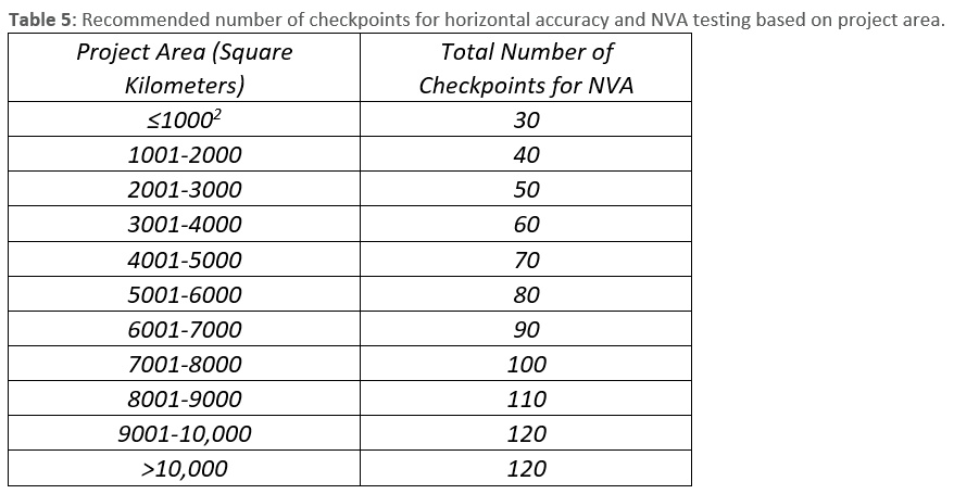
Table 5 recommends the use of a minimum of 30 checkpoints for a project area of 1000 square kilometers or less and a maximum of 120 checkpoints for a project area larger than 10,000 square kilometers. Checkpoints should be evenly distributed across the project area as much as possible. Considerations made for challenging circumstances—such as rugged terrain, water bodies, heavy vegetation, and inaccessibility—are acceptable if agreed upon between the data producer and the client. Details on the best locations for these checkpoints are provided in section 7.12 of the standards.
Testing VVA
If the project requires the VVA to be tested, there should be a minimum of 30 VVA checkpoints regardless of the project area. The data user and data producer may agree to collect a larger number of checkpoints. To avoid situations where errors in checkpoints in the vegetated terrain do not follow a random distribution, no combined statistical terms, such as RMSEv, should be used in evaluating the results of the test. In other words, only individual elevation differences (i.e. errors) for each checkpoint shall be used in the evaluation.
Accuracy of checkpoints
According to Edition 2, checkpoints used to assess any product accuracy (horizontal, vertical, or 3D) should be twice as accurate as the tested products.
Testing and reporting of product accuracy:
New to the standards is the way accuracy is computed. The following formula represents the updated and accepted method for computing product accuracy:
For the purposes of demonstration, suppose you were provided with five checkpoints to verify the final horizontal and vertical accuracy for a dataset (this example uses fewer checkpoints than the minimum 30 for the sake of brevity) according to these standards.
Table 6 provides the map-derived coordinates and the surveyed coordinates for the five points. The table also shows the computed accuracy and other relevant statistics. In this abbreviated example, the data is intended to meet a target horizontal accuracy class of RMSEH = 15 cm and a target vertical accuracy class of RMSEV = 10 cm.
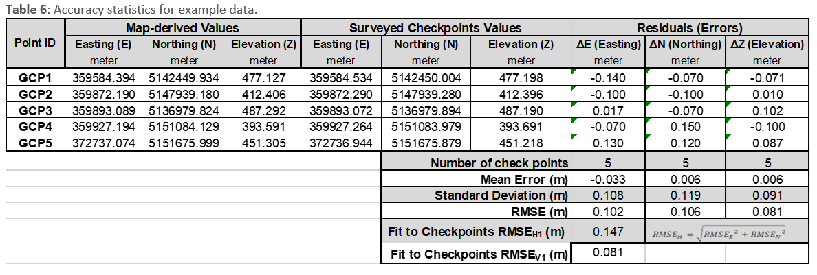
Computation of horizontal, vertical, and 3D accuracy
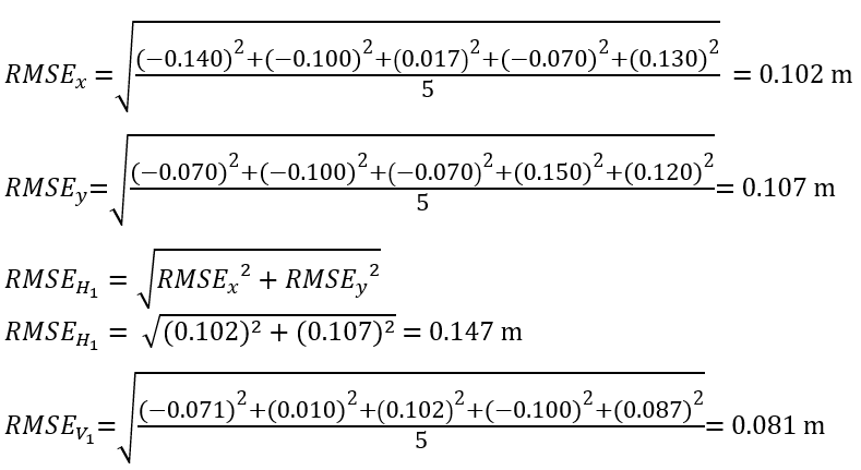
2. Compute the final accuracy values:
To complete the accuracy computations, let us assume that the checkpoint report submitted by the surveyor states that the field survey was conducted using an RTK-GNSS-based technique to an accuracy of:
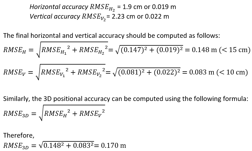
Based on the computed horizontal and vertical accuracy numbers above, the product is meeting the specified horizontal and vertical accuracies of 15 cm and 10 cm, respectively.
Final notes
The material in this article is intended to shed light on important aspects of the new edition of the ASPRS Positional Accuracy Standards for Digital Geospatial Data. Readers are encouraged to review the standards for full clarity and edification. Edition 2, version 1.0 includes only two of the five addenda. The remaining three Addenda listed in the Table of Contents will be available for public comment in the coming weeks and will be added to Edition 2, Version 2.0, which ASPRS anticipates approving in late Fall 2023:
- Addendum III: Best Practices and Guidelines for Mapping with Photogrammetry
- Addendum IV: Best Practices and Guidelines for Mapping with Lidar
- Addendum V: Best Practices and Guidelines for Mapping with UAS
To download the Edition 2 document, visit https://publicdocuments.asprs.org/PositionalAccuracyStd-Ed2-V1
Acknowledgment
Dr. Qassim Abdullah would like to extend his gratitude to all individuals who assisted in drafting Edition 2 of the standards, especially members of the ASPRS Positional Accuracy Standards Working Group, Dr. Riadh Munjy of California State University, Fresno; Josh Nimetz of USGS, Michael Zoltek of GPI Geospatial, Inc.; and Colin Lee of the Minnesota Department of Transportation. Additionally, he would like to recognize the teams who worked on drafting the addenda on best practices and guidelines, led by Jim Gillis of VeriDaaS Corporation; Dr. Sagar Deshpande of Dewberry; Dr. Nora May of Fugro; Jacob Lopez of Towill, Inc.; Dr. Christopher E. Parrish of Oregon State University; Martin Flood of GeoCue, Leo Liu of Inertial Labs, Munjy; and Zoltek. He would also like to extend his appreciation to the ASPRS staff under the leadership of Karen Schuckman, who was instrumental in reviewing the draft and providing valuable suggestions and comments. He is grateful to Alan Mikuni of GeoWing Mapping, Inc., who volunteered his time to proofread all drafts.
This article is published concurrently in Photogrammetric Engineering & Remote Sensing