
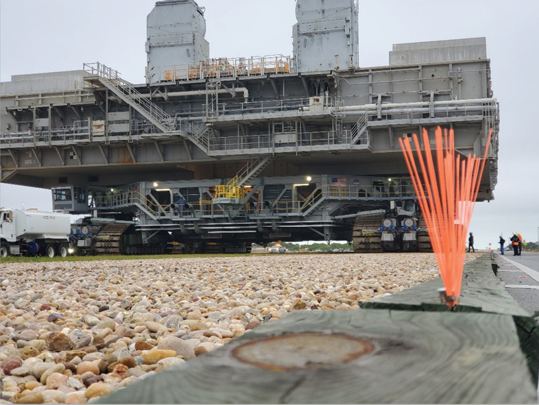
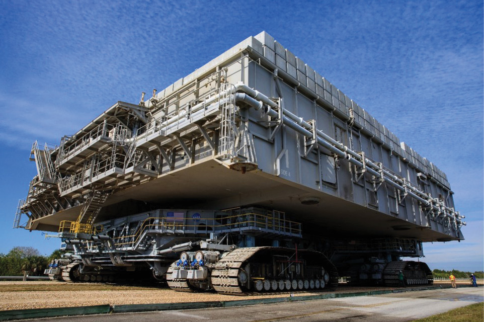
Figure 1: CT fully loaded with concrete blocks. Total weight for this pass was 25 million pounds. Photo credit Gary McDaniel.
NASA plans to launch the Orion spacecraft on a 26-day mission around the moon via the Space Launch System, its new heavy-lift rocket, in late 2021. The unmanned Artemis I flight is the first in a line of complex missions aimed at enabling exploration of the Moon and Mars.
But before the Orion spacecraft can be launched into space, it must first be moved from the Vehicle Assembly Building to the launchpad at the Kennedy Space Center.
Enter the Crawler-Transporter (CT; Figure 1), four connected building-sized vehicles on rolling tracks, which, when loaded with the Orion and its mobile launcher, will carry over 25 million pounds. That’s the equivalent of 1020 school buses, one of the heaviest overland loads ever recorded.
The challenge of moving 25 million pounds
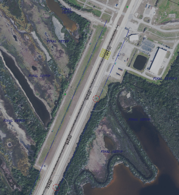
Figure 2: Map of all control points used, instrument and backsight setup locations, special monitoring areas, and CT zones of influence. The Vehicle Assembly Building (VAB) is at lower left and the launchpad, upper right. The total zone of influence is delineated by the dark blue line. The yellow arrow points North. The scale bar is in feet. Map credit Gary McDaniel.
As the CT moves along the crawlerway (Figure 2), it has the potential to sink into the ground, tip and allow its payload to fall off (Figure 3). The resulting damage could put the entire Artemis I mission in jeopardy, not to mention the more than $20 billion NASA has invested in the Orion.
To address this risk, the agency partnered with engineering firms Langan and Jones-Edmunds to monitor ground deformation under the CT in real time. The solution Langan developed was a surveying process for taking measurements on both sides of the CT simultaneously, collecting data every 10 feet along the 4.1-mile crawlerway.
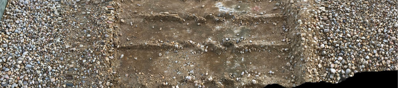
Figure 3: Crawlerway road after the CT has passed over. This shows the effect on the crawlerway, but it was determined before the survey began that the movement of the CT could affect elevation anywhere in the zone of influence. Photo credit Bryan Merritt.
The hardest part: they needed to survey the CT in motion, making the project exponentially more complex.
The process required establishing hundreds of control points as part of the baseline setup. Real-time surveying of the CT involves a team of 14 professionals working together, their movements carefully timed as the CT creeps along at roughly 26 feet per minute. Designing the solution took a full two years—and had to account for many moving parts.
Deconstructing the surveying project
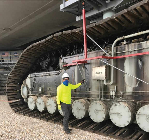
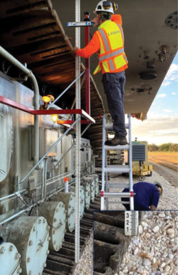
Figure 4: Finished bracket mounted to the CT truck (left)— 2” square tubing 11 feet long, 4 feet high, supported with 3/4” steel tubing, all attached without damaging or altering the surface of the CT. Measuring the height of prism relative to the crawlerway road underneath the CT trucks (center). Testing prism bracket and potential monitoring procedures during a planned move of the CT (right).
The first step of the project involved mounting surveying prisms on the CT without altering the CT itself, which the Langan team achieved using high-strength brackets (Figure 4). The second step was conducting trials to develop observation procedures and timing for surveying teams.

The primary control network with over 100 control points was established prior to the monitoring surveys. GNSS was used to determine the horizontal positions of these points and a closed differential level loop run to determine their elevations.
Trees and brush in the area mean that surveying stations must sit within the CT’s zone of influence (Figure 6), defined as the theoretical distance from the CT within which, according to mission engineers’ estimates, the soils could potentially be disturbed by the movement of the CT.
There was only one problem
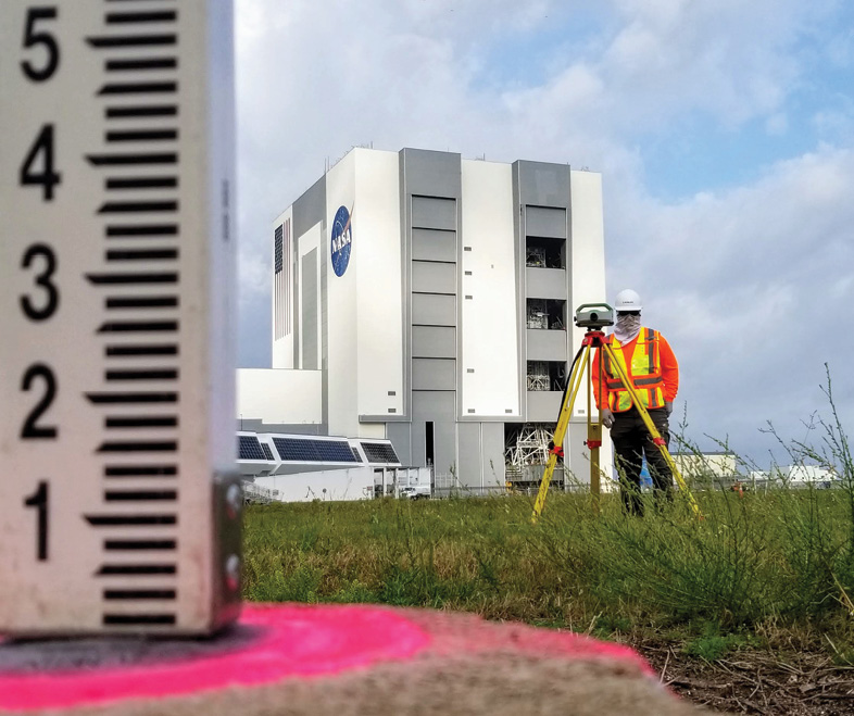
Figure 5: Vertical control survey: a closed digital level loop was used to establish elevations for all control points set (left). Control level run started from an NGS monument near the VAB (center and right). Photo credits Ryan Wolf.
Inside the CT’s zone of influence, the weight of the CT could move the ground under the surveying equipment itself, impacting the accuracy of the data. To account for this risk, Langan set up a secondary survey control network outside the zone of influence, effectively doubling the number of measurements taken.
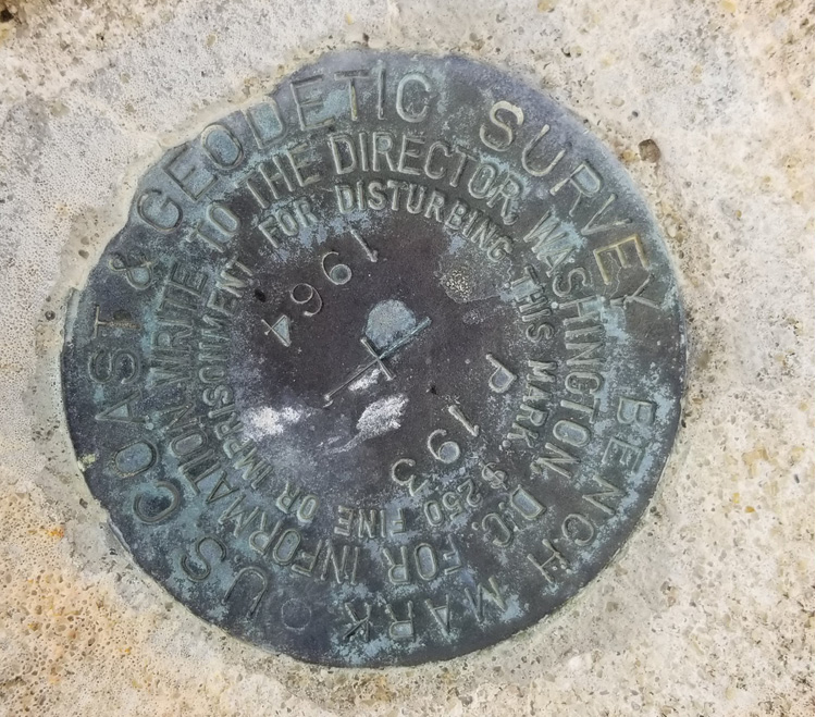
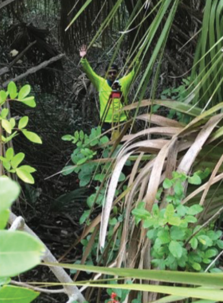
Figure 6: Vegetation close to the crawlerway road sometimes meant that to get outside the CT zone of influence levels had to be set up 40 or 50 feet into the trees. Photo credit Gary McDaniel.
During the monitoring survey (Figure 8) each total station was set on its assigned primary control point(s) and used to observe a 360° prism set at a fixed height on another primary control point. The 360° prisms on fixed height rods were used to allow multiple total stations to simultaneously use each “backsight prism” to orient the survey and could be also be used as quality control checks by other total stations.
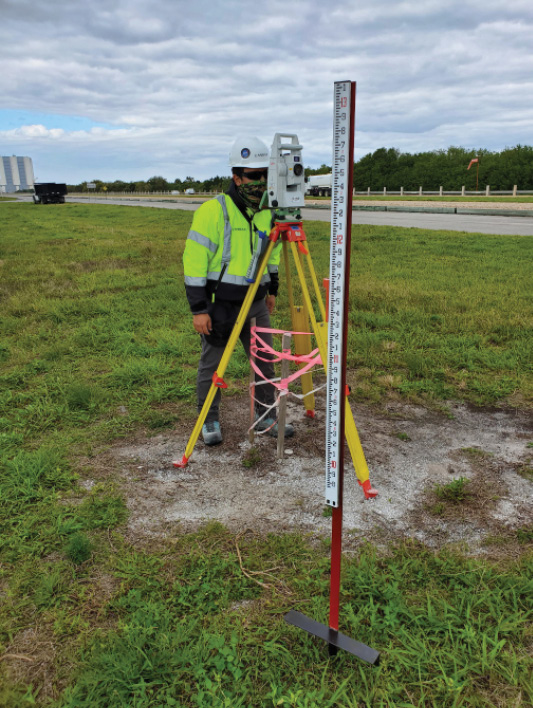
Figure 7: Monitoring the elevations. 12” square aluminum plate fixed to the bottom of a survey rod to allow for a measurement of the top of the crawlerway road surface, ensuring the rod tip did not fall between individual rocks (left). Bespoke mount for level rod to monitor ground at an instrument setup within the CT zone of influence (center). Monitoring the ground at an instrument location outside the CT zone of influence (right).
Once the CT was within range the instrument operators would look through the total station to fix the crosshairs upon the 360° prism mounted to the CT. This was needed to allow the robotic total station to automatically and continually track the prism and make constant calculations about how far the prism was from its last recorded position. Once a distance of 10 feet from the previously recorded position was achieved, the data collector would store the prism coordinates (X,Y,Z) and use the newly stored position as the updated reference position to prepare for the next upcoming measurement. This procedure allowed us automatically to take measurements of the CT every 10 feet utilizing the technology of the robotic instruments. Team members would then enter the elevation of the recorded measurement into a spreadsheet that was used to aggregate the measurements from all four total stations being used.
Dry run

Figure 8: The monitoring process. Top-left: Langan survey crew in position ahead of the CT, prepared to monitor once the CT moves within range. Top-right: CT being monitored from a control point setup within the zone of influence. Lower-left: One member walking with CT calling out station marks, one at total station taking measurements to the prism mounted to the CT, one at the instrument recording data in shared spreadsheet on a field tablet, one using a level placed outside the CT zone of influence to monitor the ground underneath the total station. Lower-right: Station markers were set every 50 feet along the entire length of the crawlerway.
The last step—a dry run of the surveying process—is where the team’s preparation was put to the test. Four robotic total stations are used, with two crews on each side of the CT leapfrogging each other as the CT moves down the path. While one crew measures the location and elevation of the surveying prism on the CT, the other moves into position for the next measurement.
Langan sends the measured data to a shared spreadsheet within seven seconds, using a formula to determine whether any ground deformation detected is within normal limits. At that point, the Jones-Edmunds team is responsible for deciding whether it’s safe to keep rolling or whether the CT must stop.
The final test, however, will come when the CT finally carries the Orion to the launchpad. That day will represent years of preparation in support of a groundbreaking mission decades in the making, one that will help humans reach new frontiers in space.
Social posts
Learn how Langan is helping prepare for the upcoming @NASAArtemis #space mission #surveying #engineering #NASA; or how Langan is using real-time #surveying of a moving object to support the @NASAArtemis #space mission #engineering #NASA
Bryan Merritt, PLS/PSM is a Professional Land Surveyor licensed in New York and Florida. He serves as a Senior Survey Manager in charge of Florida and the Caribbean for Langan Engineering and Environmental Services Inc. He has been surveying since 1982 and has an extensive background in all facets of surveying methodologies.
Gary McDaniel, PSM started surveying in 2012 after teaching high school physics and chemistry for seven years. He earned his Professional Survey and Mapper License in Florida in 2019 and has been a licensed sUAS pilot since 2017.