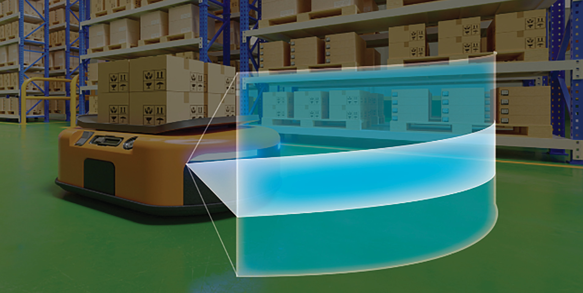
Figure 1: Small, low-power, and short-range lidar modules can create a cocoon of visibility around robots and vehicles to enhance safety and enable new capability, such as a self-parking feature.
Most people associate lidar with long-range applications: aerial mapping, or those domes atop experimental autonomous vehicles. But lidar’s most exciting story may come from short-range (10-20 m) applications and small form factors. The same benefits that have revolutionized airborne surface mapping and vehicle navigation are spilling out a cornucopia of new uses. The value of lidar is just as compelling at 2 m as at 200 m: piercing complex and ambiguous lighting to find physical surfaces, and attaching correct distance data to each point in a scene. Together these abilities all but eliminate catastrophic errors and vastly reduce computation for the software that must turn pixels into recognized objects and an accurate 3D map of a scene.
Small, low-power, and short-range lidar modules can strengthen active safety and improve mapping and navigation for industrial machinery, robots, and drones (Figure 1). If small enough, they can vastly improve augmented reality apps for smartphones. For proof, see the iPhone 12 Pro.
Range, size, power
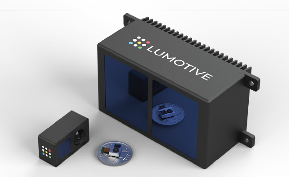
Figure 2: The Lumotive LCM solid-state beam-steering technology allows lidars to be scaled from short-range, tiny modules for smartphones, to golf-ball-sized lidars for short-range automotive and industrial applications, and all the way to high-performance, long-range lidar for self-driving applications.
Small systems can benefit greatly from lidar, but they can’t support the size, weight, power consumption, or cost of today’s big, long-range systems. Fortunately, all four of these factors can be improved by reducing the required operating range to much less than automotive lidar’s 250 m.
Reduce the range to, say, 20 m for ADAS or industrial/robotics use, and you can use a lower-power laser, less expensive optics, and a package the size of a golf ball. Reduce a bit more, and you can make a lidar in the size and power range of a smartphone camera module (Figure 2). But both of these reductions depend on one critical—and non-trivial—technical feat: eliminating the moving-mirror assembly that steers the laser beam to illuminate the field of view, and that, with its mirrors, bearings, and positioners, stubbornly refuses to scale down.
Doing it without mirrors
It is possible to eliminate the moving-mirror subsystem. The easiest approach is called flash illumination. Like a camera flash gun, the lidar in a flash system illuminates the entire field of view with a single pulse. A lens focuses an image of the scene on a 2D time-of-flight (ToF) sensor, and each pixel in the sensor records the phase difference between the flash and the arrival of reflections from the scene. From these phase differences, the system can determine the distance from the lidar unit to each point imaged in the field of view.
The system is mechanically simple but has serious challenges. The energy of the flash is spread across the entire field of view, so the reflected pulse at any one point has little energy, and is easily lost in the glare of sunlight. In bright sunlight, it takes a heroic flash to give the sensor anything at all to detect. This is why the flash lidar in the Microsoft Kinect works well in dimly lit rooms, but is essentially blind in daylight.
Nor is ambient light the only issue. Multipath—when the flood of light can take more than one path from the flash illuminator to a point in the scene and back to the sensor—can cause spurious range measurements, distorting the shape and distance of objects. This artifact is especially problematic in a scene with reflective surfaces. And interference—when multiple lidar units operate in the same area, as in a warehouse with multiple robots or in a multiplayer game—can also cause incorrect range readings.
Modified flash
Cleverness can help. For example, Apple engineers refined the flash approach for the iPhone 12 Pro by adding an optical element in front of the flash unit that shapes the light from the VCSEL1 not into a flood, but into a 24 x 24 array of discrete beams spread evenly across the field of view. Hence more energy strikes each illuminated point in the scene, overcoming the ambient light so the system can function outdoors. The discrete beams also help, but do not eliminate, the multipath and interference problems. But with this architecture, the limited number of beams—576—produces a very low-resolution depth image. Such coarse resolution can distort the shape of irregular objects, and can miss smaller objects altogether, even if they are critical to the application.
Solid-state beam steering
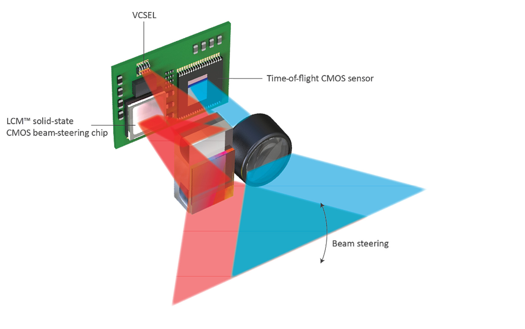
Figure 3: In a Lumotive lidar module, the LCM sweeps the reflected row of light through a coupling prism and over the field of view. A lens focuses light reflected from the scene (shown in blue) on to a 2D time-of-flight (ToF) sensor. By synchronizing the illumination of rows in the field of view with the readout of rows from the ToF sensor, the system can efficiently create high-performance 3D images of the scene in a process similar to rolling shutter.
Moving-mirror systems overcome the ambient light and other issues of flash by concentrating all of the VCSEL energy in a single beam, but they are nearly impossible to scale. Flash systems can scale to small sizes and lower power, but they struggle with ambient light, resolution, and other accuracy issues. However, a remarkable application of physical optics using conventional liquid-crystal technology allows an escape from this dilemma. The trick is a solid-state device—a CMOS chip—that provides motionless beam steering.
The heart of this architecture is that chip, which Lumotive2 calls a liquid-crystal metasurface (LCM). Envision a small CMOS integrated circuit overlaid with a thin array of tiny liquid-crystal cells—so tiny that they can be spaced on a ¼-wavelength pitch. At this size, the cells can act like a huge array of tiny optical antennae—reflecting an incoming beam of light at an angle determined by the voltage signals applied to the cells. In this way, a fixed LCM can sweep a beam of light across the field of view under software control.
In a Lumotive lidar module (Figure 3), a row of VCSELs illuminates the surface of the LCM. The LCM then sweeps the reflected row of light across the field of view. A lens focuses light reflected from the scene on to a 2D ToF sensor, which detects the laser illumination returning from the scene. After each sweep—requiring about 50 ms—the ToF sensor provides a 640 x 480 array of range data.
This approach has significant advantages. Because each point in the field of view gets a significant portion of the energy from the VCSEL row, the LCM lidar can reduce the power of the lasers about 10X compared with what a flash approach would require, or the LCM lidar can offer two to three times the effective range at similar ambient light conditions. Resolution is limited by the ToF sensor, not the illumination, providing more accurate shapes for surfaces in the scene and catching far smaller objects. Because only a stripe across the field of view is illuminated at any one time, multipath and interference are significantly reduced as well. Another key advantage is that because LCM beam steering doesn’t have any mechanical inertia, the beam can be steered in any order across the field view, all under software control. For example, an application can switch from a uniform scan of the entire field of view to a narrower, faster scan of a limited area to collect more data on an object of interest.
Equally important from a system vendor’s point of view, the materials and processes used are familiar and mature—in fact, all the base technologies are already used in smartphones. So Lumotive can scale the lidar to golf-ball or camera-module size at commercial volumes.
We have seen that a small, low-power, inexpensive lidar would open new vistas of compelling applications. But moving-mirror beam won’t scale. Moreover, flash approaches that eliminate the moving mirrors suffer from significant performance challenges. Lumotive offers a scalable architecture based on our proprietary solid-state beam-steering LCM chip, shattering the dilemma and opening new worlds of compelling applications.
1 Vertical cavity surface emitting laser.