The lack of primitive surfaces in natural scenes presents a challenge for adjusting and validating UAS lidar data. Researchers at the University of Florida have found a unique solution.
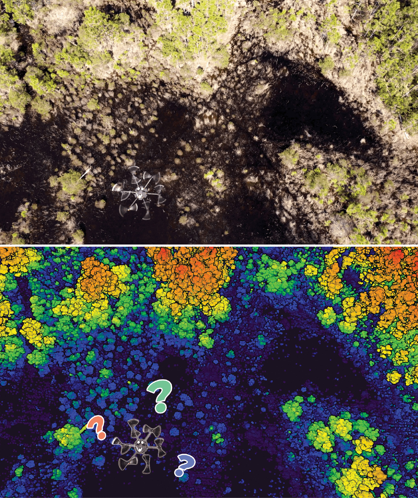
Researchers at the University of Florida have been working with UAS lidar for several years. This includes low-level investigation into the sensor and platform technology as well as collaborative projects with a variety of scientists and managers including those involved in wildlife biology, forestry, and ecology. We have collected point clouds in areas from dense forests to sandy beaches, almost always in some rural locale away from buildings, roads, and other convenient, regular structures that facilitate processing and validation. Early on, we ran into the problem of identifying discrete locations in these point clouds to perform adjustment, in situ calibration, and accuracy assessment. Like many other users, we first explored using flat targets, relying on intensity to find them in the point cloud. The inconsistency of intensity values from the systems, however, made it difficult to discriminate the targets from the background, particularly in natural scenes. We found that precisely identifying the horizontal reference point of these flat targets, usually the center, was also difficult, depending on the distribution of points that fell on it.
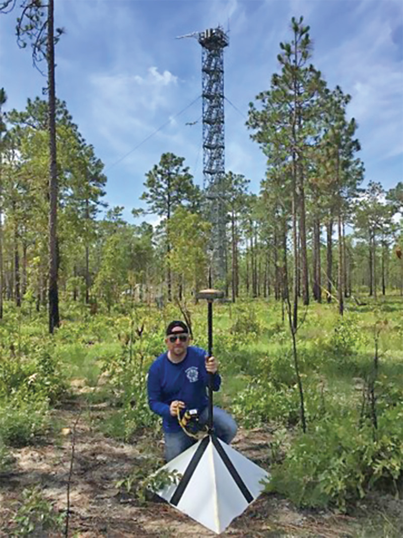
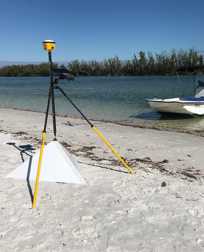
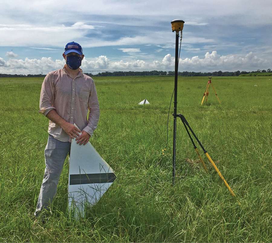
Figure 1: The targets deployed at various locations.
To address this, we developed a “geometric” UAS lidar target. The target is a trilateral pyramid, i.e. the base is a triangle, and the intersection of the three planes that slope upwards from the base serves as the reference point, allowing for precise determination of both the horizontal and vertical components of locations within the point cloud (Figure 1). The base of the pyramid has sides about one meter long and the structure measures about 40 cm from base to tip. With the help of a local artist who specializes in foldable, morphing installations, the target was designed to fold flat for storage and transport. Since it is made of corrugated plastic, it is light, and about twenty can be carried by a single crew member.
 Geometric targets for lidar are not a new idea. Practitioners have used spheres, cylinders, elevated reflector arrays and other designs—many can recall Dr. Toth’s trampolines. Similarly, using the intersection of planes to measure 3D locations within a point cloud is also a well explored idea, exemplified by the excellent work of USGS on using these features for accuracy assessment. Here we outline our approach for automatic measurement of the pyramidal UAS lidar targets.
Methodology
 The target measurement method is template-based. In other words, the planes of the target are not pre-identified or solved and intersected initially. Since the shape of the target is known, an iterative least-squares solution is used to fit a 3D template to the points in the neighborhood of the target in the point cloud. This works by minimizing the sum of the squares of the distances of candidate points to their (iteratively selected) closest facet. The major steps of the algorithm are the following:
1. Coarsely identify and isolate points on the targets

Figure 2: Coarsely identified candidate target points in the vicinity of the target. Scale bar in meters.
Begin with a small section of the point cloud which fully contains the target (Figure 2). Because the algorithm will automatically cull non-target points, one can be aggressive in choosing these candidate sections: careful snipping is unnecessary. The only requirement is that the highest point in the snip should be near the target apex.
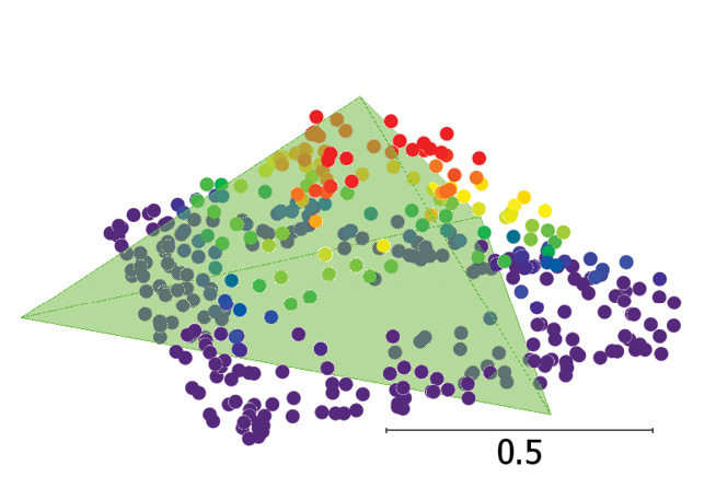
2. Initialize the target reference location
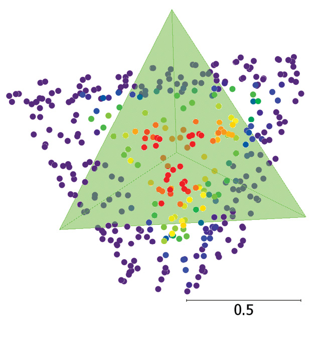
Figure 3: Top and side view of automatically initialized template/reference point location. Scale bars in meters.
The top of the pyramid template is initialized at the highest of the candidate points, the base is initialized as level, and the azimuth can be arbitrarily initialized and still lead to convergence (we always initially align one edge in the east-west direction). See Figure 3.
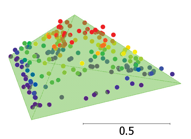
3. Iterative least-squares solution
 An iterative least-squares solution is used to solve for the 3D angular orientation and position of the target template within the point cloud (Figure 4). Each iteration requires recalculation of point-facet associations, since the template can move quite a bit from the initial position. Rejected points are excluded from the observation equations.
4. Determine target position from least-squares solution
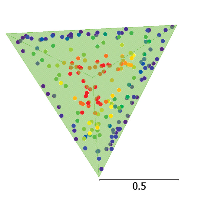
Figure 4: The solved template location. The reference point location is the peak of the pyramid. Note that non-target points have been automatically removed. Scale bars in meters.
Recall that the reference point of the pyramid—its top—was initially set to the highest point among our candidate points from the initial snip. The least-squares solution solves for the translation of that initial point (the rotation from its initial orientation is also part of the solution). Applying that translation gives us the estimated coordinates of the reference point in the point cloud.
5. (Optional) resolve the reference point by solving for the three planes and their intersection point.
 With a solution for the measured pyramid in hand, we can determine which face of the pyramid each point belongs to. As a further check on our work, we can fit a new plane to each of the three groups of points and solve for the intersection of the three planes. This solution should be close to the results of step 4, and can serve as a check on the solution.
Precision of the results
A benefit of using a least-squares approach to resolving the reference point is that the estimated uncertainty of its location can be derived. The uncertainty is closely linked with the number of points incident on the target. Experiments indicate that for typical, easily obtainable point densities >100 pts/m2, the reference point can be found with an estimated uncertainty of σ = ١ cm for X, Y, and Z. This was corroborated with experiments where the targets were field-measured using PPK GNSS with the same base-station as that used to process the trajectory of the lidar UAS. It should be mentioned that these results are under ideal circumstances, and various mission parameters can influence the results, including flying height and scan angle, and similarly these estimated uncertainties should not be conflated with absolute accuracy of the point cloud, which is likely much poorer. Experiments have also shown that point distribution, for example only a few points falling on one of the target facets, does not substantially hinder measurement. Along the same lines, the effect of the distribution of points is reflected well in the estimated uncertainty, prompting manual inspection of located targets having high standard deviations.
Issues to be considered
Using the targets for many field collects has led to the discovery of some potential issues and development of mitigation strategies. For example, in high wind, the targets can become airborne due to their shape and light weight. Since they are made of plastic, it is easy enough to stake them to the ground, as long as care is taken not to warp any of the facets. Another potential issue is that very low-density UAS point clouds may lead to bias in the height component. This is typically not a problem, unless the target is under canopy or at the project edge. One solution is to constrain the tilt of the template in the estimation algorithm, holding it fixed as level, but this can be done only if the ground is relatively flat and level. Another major consideration is that the shape of the targets theoretically weakens resolution of the height component compared to flat targets. A solution to this when using the targets as checkpoints is placing a flat target next to the base of the pyramid, say on the west side, for height measurement or as a check on the height of the 3D pyramid target.
Use of the targets
The targets can be and have been used in accuracy assessment, calibration, adjustment, and as control points. Depending on the goals and requirements of an accuracy assessment, the targets can be surveyed using a level and total station, or by using GNSS. The 3D-printed cap for the pyramids, designed by Connor Bass, an MS student at the University of Florida’s Geospatial Mapping and Applications Lab, and shown in Figure 1, may be used to precisely place a GNSS antenna directly over the reference point. For strip adjustment or boresight calibration, several targets may be placed in an array so that they are covered from multiple flight lines, at varied locations within swaths, and from diverse perspectives. The point clouds may then be adjusted in one of two ways based on the density of the point cloud. Since the algorithm automatically identifies points that fall on the pyramid, they may be isolated from the rest of the points in the point cloud. The adjustable parameters, e.g., the strip transformation parameters or boresight calibration parameters, may then be estimated by finding those that minimize the sum of the squares of the distances to the template facets. The template parameters may also be included in the unknown parameters using this method. In the case of sufficiently dense point coverage, another method is to separate target points into flight lines or collection units and find the adjustable parameters using optimization based on the iterative closest point algorithm.
Conclusion
The pyramid targets described here have been a successful addition to our fieldwork and processing/analysis workflow. The ability to locate discrete features, particularly in remote rural locations, helps to ensure accurate and reliable final products along with an avenue to precisely check the data. The simple design can and has been replicated by others, and the mensuration algorithm is similarly simple and includes uncertainty estimates to inform the proper use of the coordinates. For more information on the targets, including a more detailed look into the algorithm and experiments validating the uncertainty estimates and point distribution requirements, please see the journal article below.
Reference
Wilkinson, B., H.A. Lassiter, A. Abd-Elrahman, R.R. Carthy, P. Ifju, E. Broadbent and N. Grimes, 2019. Geometric targets for UAS lidar, Remote Sensing, 11(24): 3019. 20 pp.
Dr. Ben Wilkinson is an Associate Professor at the University of Florida’s Geomatics Program and co-director of the Geospatial Mapping and Applications Lab (GMAP). His research focuses on photogrammetry, lidar, and UAS.
Dr. H. Andrew Lassiter is a postdoctoral associate in GMAP. His most recent work includes sensor modeling for optimizing UAS lidar and photogrammetric data acquisition.