Surveying and mapping technologies have advanced tremendously over the last century, resulting in improved product accuracy. Yet some antiquated practices and processes continue, as if they are frozen in time. This article will focus on an outdated practice that needs to be addressed: the way we evaluate the positional accuracy of geospatial products.
Before detailing this problem and introducing the correct approach, we should establish a basic understanding of how to determine and report product accuracy, geometric datum, and what that datum represents. To understand the datum, one needs to know how we deal with the shape, or figure, of the Earth.
Author’s note: This article published concurrently in PE&RS and LIDAR Magazine
Figures of the Earth
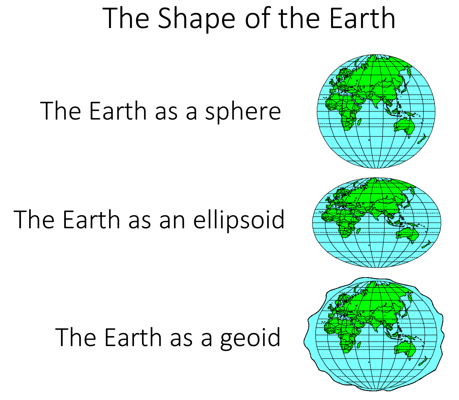
Figure 1: Shapes of the Earth (Courtesy of Esri documentations).
The physical surface of the Earth is the shape we attempt to model through our mapping or surveying practices. However, because of irregularities on the Earth’s surface and the lack of a comprehensively surveyed model of that surface, several geometrically defined shapes are employed in our surveying and mapping techniques to approximate the Earth’s surface to determine specific geographic locations (Figure 1). These geographic locations must be referenced by a well-known system called a “datum.”
Earth as an Ellipsoid
An ellipsoid surface is obtained by deforming a sphere by means of directional scaling, so it is the best shape to use to approximate the Earth. The term datum is nothing but an ellipsoid with defined axes, curvature, a known origin in space and axes rotation. Wikipedia defines the Earth ellipsoid as “a mathematical figure approximating the Earth’s form, used as a reference frame for computations in geodesy, astronomy and the geosciences.” Datum origin can be positioned at any place in space. The origin of the NAD27 datum is at the survey marker of the Meades Ranch Triangulation Station in Osborne County, Kansas. Geocentric datum is a datum with its origin positioned at the mass center of the Earth. Examples of geocentric datums are the NAD83, ITRF and WGS84—all of which are based on the GRS80 ellipsoid. All surveying and mapping activities, including GNSS surveying, determine how far a position on the Earth’s surface is from the surface of a referenced ellipsoid or geoid.
Earth as a Geoid
A geoid represents the equipotential surface of the Earth’s gravity and comes very close to mean sea level. Wikipedia defines a geoid as “the shape that the ocean surface would take under the influence of the gravity and rotation of the Earth alone, if other influences such as winds and tides were absent.” Surveyors traditionally present their height measurements in reference to the geoid, i.e. how far that position is above or below the geoid surface. Since the geoid surface is shaped by the same gravitational force that causes water to flow downhill, people like to survey elevations by referencing the geoid because those elevations or slope directions align with that natural water flow. Conversely, ellipsoidal heights measuring up or down slopes may not match that water flow direction.
The True Physical Shape of Earth
The terrain around us is irregular and does not coincide with either geoid or ellipsoid surfaces. Our surveying and mapping activities are solely conducted to represent the physical figure of the Earth on a map or within a geospatial database as it is referenced to the datum.
Surveying to Represent the True Datum
When we conduct field surveying, we are trying to determine terrain positions and shapes in reference to a specific geodetic datum. According to the U.S. National Geodetic Survey (NGS), a geodetic datum is defined as “an abstract coordinate system with a reference surface (such as sea level, as a vertical datum) that serves to provide known locations to begin surveys and create maps.” Because our surveying techniques, and therefore our mapping techniques, are not perfect, our surveying results are approximate positions that put us close to the true, datum-derived positions (Figure 2). When we use an inaccurately surveyed network to control another process such as aerial triangulation, in reality we are fitting the aerial triangulation solution to an observed datum. The degree of approximation depends on the surveying technique or technology employed in that survey. The Real-Time Kinematic (RTK) field surveying technique can produce positions that are accurate to 2cm horizontally and perhaps 3cm vertically. The differential leveling technique used to determine height can produce elevations that are accurate to the sub-centimeter. The lesson to learn here is that our surveying techniques, no matter how accurate, do not represent the true datum—but they can get us close to it.
Surveying and Survey Datum
When we task surveyors to survey the ground control network in reference to a certain datum, they can only determine the positions of the control network to that datum as close as the surveying techniques allow. In other words, the coordinates that are being used to control the mapping process represent an observed or survey datum that represents a pseudo datum but not the original intended or true datum (Figure 2). For example, if we are trying to determine point coordinates in NAD83(2011), the surveyed coordinates used in aerial triangulation or lidar calibration represent a datum that is close to NAD83(2011) but not exactly NAD83(2011) due to the inaccuracy in our surveying techniques. That inaccurate survey represents a survey datum. Besides the inaccuracy in the surveying techniques, another layer of errors (i.e. distortion) is added to the surveyed coordinates when we convert geographic positions (in latitude and longitude) to projected coordinates or grid coordinates, such as state plane coordinates systems.
Mapping To The Mapping Datum
Any mapping process we conduct today inherits two modeling errors that influence product accuracy. The first modeling error is caused by the inaccuracy of the internal geometric determination during the aerial triangulation, or the boresight calibration in the case of lidar processing. The second modeling error is introduced by the auxiliary systems, such as GPS and IMU, and has inherent errors caused by the survey datum. Therefore, when we use mapping products to extract location information, we are determining these locations in reference to the survey datum and not the original intended datum. The point coordinates for NAD83(2011) are determined not according to the survey datum of the ground control network but through a new reality of mapping datum. The mapping datum inherits the errors of the survey datum, which were caused by the inaccuracy of our surveying techniques and the errors caused by our mapping processes and techniques (Figure 2).
Drilling to the True Datum
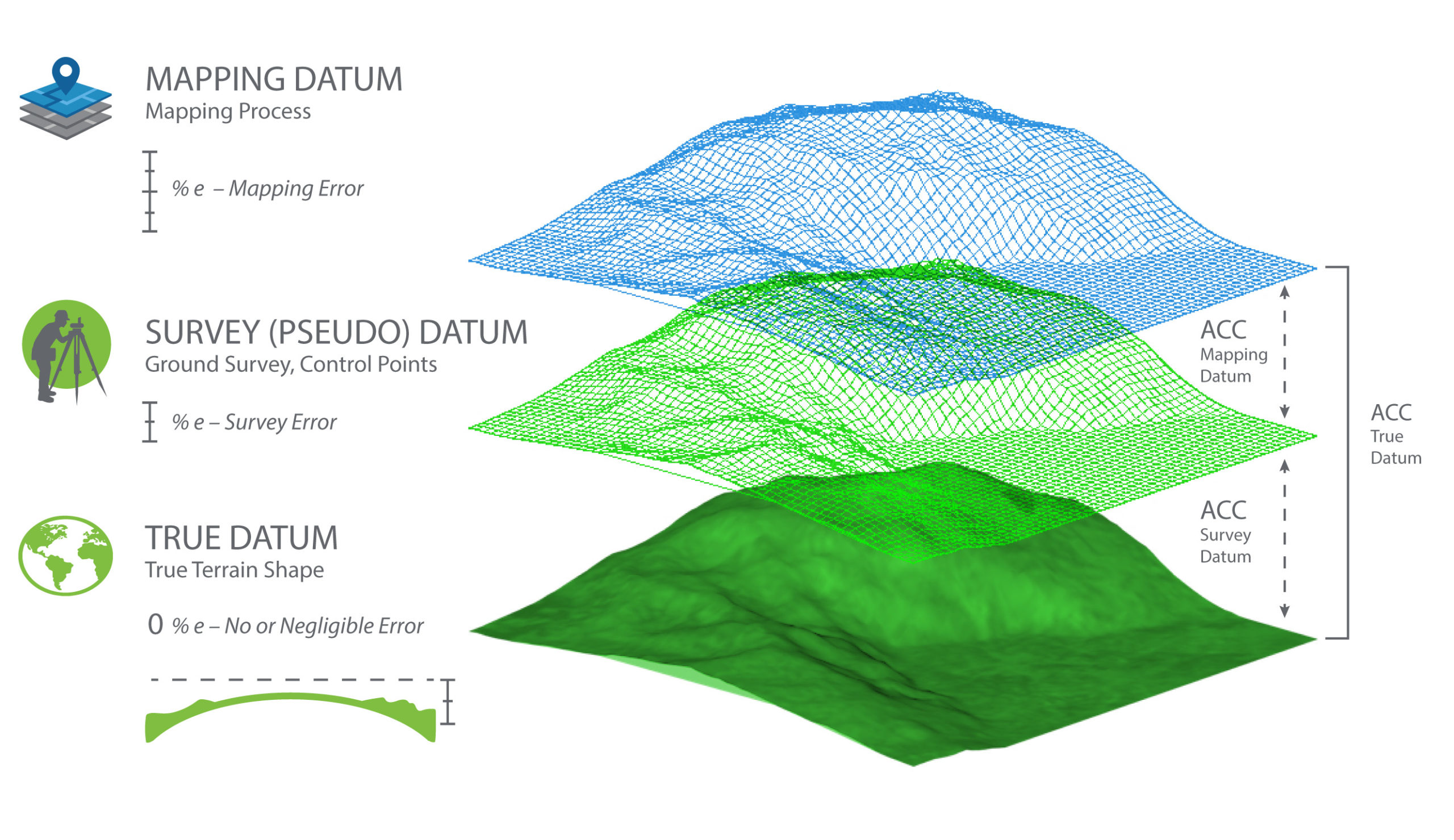
Figure 2: Datums and error propagation in geospatial data.
To reference the accuracy of determining a mapped object location within a mapping product to the original intended datum like NAD83(2011), we need to examine the layers of errors that were introduced during the ground surveying and mapping processes (Figure 2).
Product Accuracy Computation
Currently, users of geospatial data express product accuracy based on the agreement or disagreement of the tested product per the surveyed checkpoints, ignoring checkpoint errors that have resulted from inaccurate surveying techniques. In other words, users consider the surveyed checkpoints to be free of error. The following section details how errors are propagated into the mapping product when we are trying to determine the location of a ground point “A”. Let us introduce the following terms:
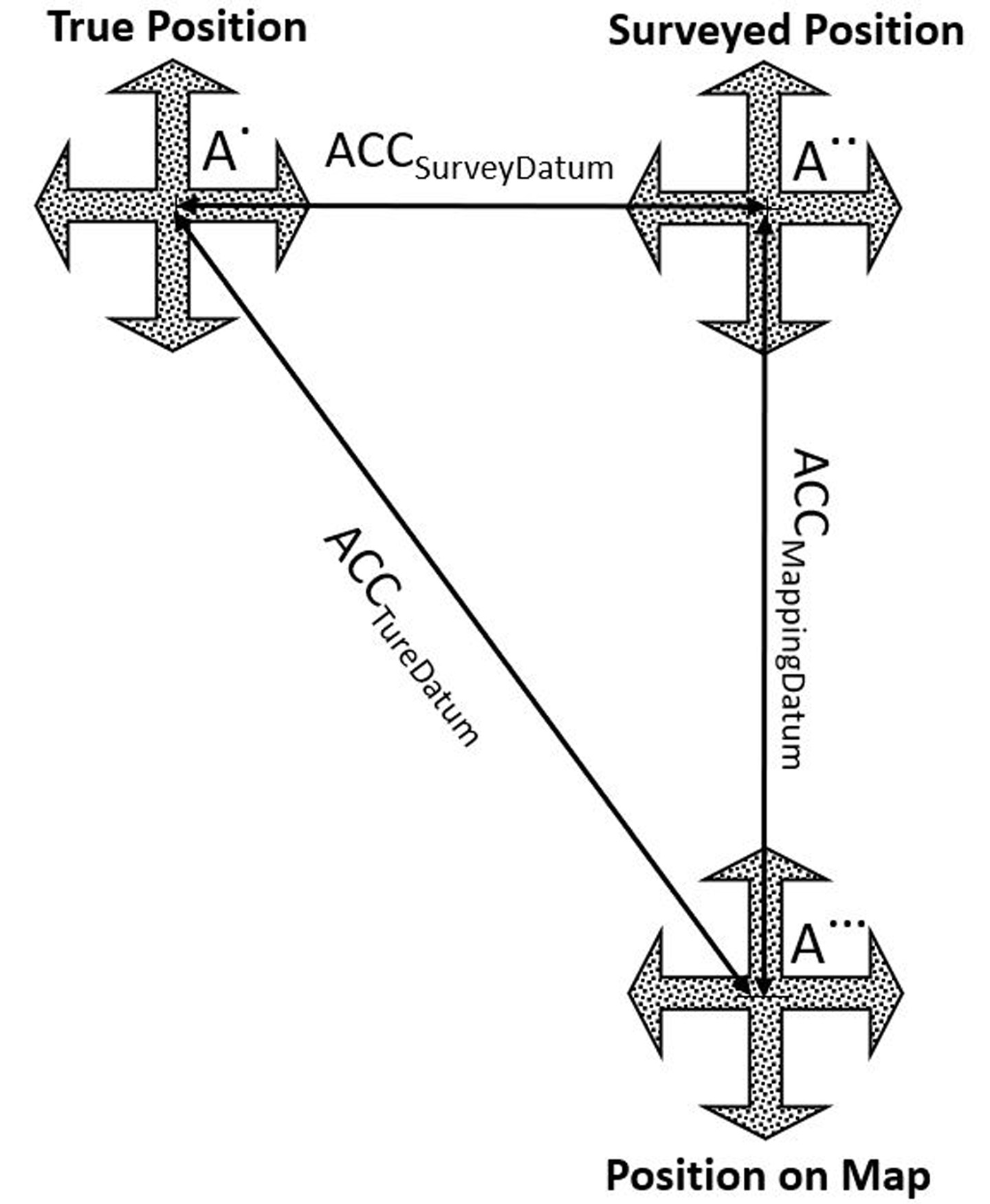
Figure 3: Influence of error propagation on point location accuracy.
ACCSurveyDatum equals the accuracy in determining the survey datum, generated when realizing the intended or true datum through surveying techniques. In other words, it represents the errors in the surveyed checkpoints. Due to this inaccuracy, the point will be located at location A.. (Figure 3).
ACCMappingDatum equals the accuracy of determining the mapping datum, or the errors introduced during the mapping process, in reference to the already inaccurate survey datum represented by the surveyed checkpoints. In other words, it is the fit of the aerial triangulation (for imagery) or the boresight/calibration (for lidar) to the surveyed ground control points represented as the survey datum. This accuracy is measured using the surveyed checkpoints during the product accuracy verification process. Due to this inaccuracy, the point will be located at location A… (Figure 3).
Figure 3: Influence of error propagation on point location accuracy.
ACCTrueDatum equals the accuracy of the mapping product in reference to the true datum, as in NAD83(2011). The point location A. (Figure 3) is considered the most accurate location determined in reference to the true datum.
Using the above definitions, the correct product accuracy should be modeled using error prorogation principles according to the following formula:
ACCTrueDatum = ![]() (1)
(1)
However, according to our current practices, product accuracy is computed according to the following formula, ignoring errors in the surveying techniques:
ACCTrueDatum = ACCMappingDatum (2)
Practical Method of Computing Accuracy Components
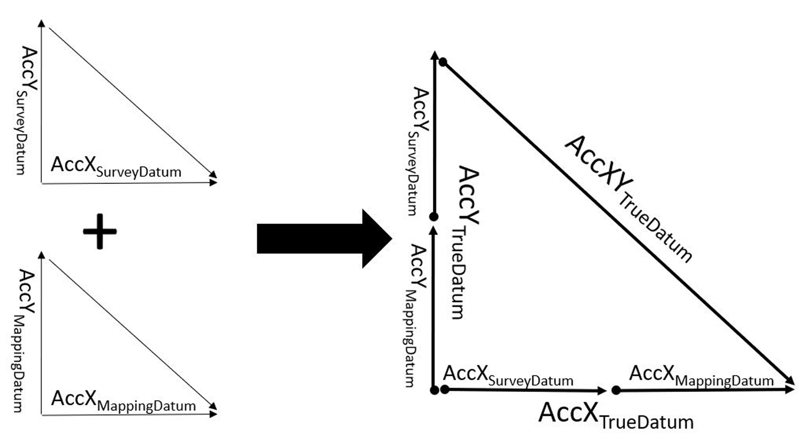
Figure 4: Vector representations of error components.
As we are dealing with three-dimensional error components, we would need to employ vector algebra to accurately compute the cumulative error.
Computing Horizontal Accuracy
To compute the horizontal accuracy for a two-dimensional map, as with orthorectified imagery, we will ignore the error component of the height survey. In other words, we will use the error component from easting and northing only. We will also assume that the accuracy of determining the X coordinates (or easting) is equal to the accuracy of determining the Y coordinates (or northing). Using error propagation principles and Euclidean vector in Figures 3 and 4, we can derive the following values for product horizontal accuracy:
AccXTrueDatum = ![]() (3)
(3)
AccYTrueDatum = ![]() (4)
(4)
AccXYTrueDatum = ![]() (5)
(5)
As an example, when modeling horizontal product accuracy according to the above formulas, let us assume the following:
- We are evaluating the horizontal accuracy for orthoimagery using independent checkpoints.
- The control survey report states that the survey for the checkpoints, which was conducted using RTK techniques, resulted in accuracy of RMSEXorY equal to 2cm.
- When the checkpoints were used to verify the horizontal accuracy of the orthoimagery, it resulted in an accuracy of RMSEXorY equal to 3cm.
Solution
Using equations 3, 4 and 5:
AccXTrueDatum = = 3.61cm
AccYTrueDatum = = 3.61cm
AccXYTrueDatum = = 5.1cm
The value of 5.1cm is the true accuracy of the product versus the following value of 4.24cm used commonly today that ignores the errors introduced during the ground surveying process:
AccXYTrueDatum = = 4.24cm
Computing Vertical Accuracy
Similarly, for vertical accuracy determination of elevation data derived from lidar or photogrammetric methods, we need to consider the error in the surveyed elevation as an important component. Using error prorogation principles and Euclidean vector of Figure 5, we can derive the following value for vertical product accuracy:
AccZTrueDatum = ![]() (6)
(6)
As an example, when modeling vertical product accuracy according to the above formulas, let us assume the following:
- That we are evaluating the vertical accuracy for a mobile lidar dataset using independent checkpoints.
- The control survey report states that the survey of the checkpoints, which was conducted using RTK techniques, resulted in an accuracy of RMSEZ equal to 3cm.
- When the checkpoints were used to verify the vertical accuracy of the lidar data, it resulted in an accuracy of RMSEZ equal to 1cm.
Solution
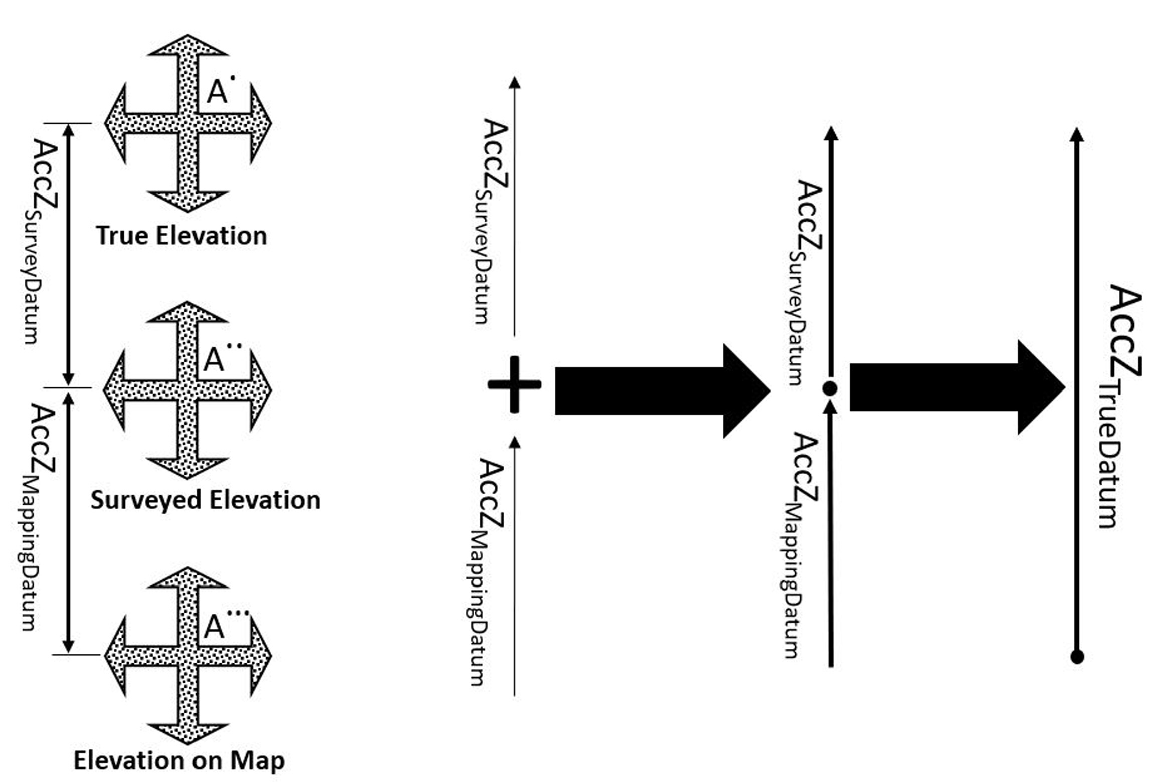
Figure 5: Influence of error propagation on point elevation accuracy.
Using Equation 6:
AccZTrueDatum = = 3.16cm
The value of 3.16cm is the true vertical accuracy of the lidar dataset versus the value of 1cm, derived by the mapping technique used commonly that ignores the errors introduced during the ground surveying process.
Remarks and Recommendations
The propagation of errors through the mapping process is a well-known and well-practiced science in surveying and mapping. However, due to the gradual evolution in mapping technologies and mapping practices over decades of advancements, users have become less sensitive to the fact that surveying techniques are not perfect. Such insensitivity is caused by the following simple facts:
- The early days of mapping products were highly inaccurate, and users ignored the errors caused by inadequate surveying techniques. Earlier in the days of digital mapping, the U.S. Geological Survey (USGS) introduced the Digital Orthophoto Quadrangle (DOQ). DOQs produced by the USGS cover an area measuring 7.5-minutes longitude by 7.5-minutes latitude (the same area covered by a USGS 1:24,000-scale topographic map, also known as a 7.5-minute quadrangle). The USGS also introduced second product that is higher in resolution and accuracy than the DOQ called the Digital Orthophoto Quarter Quadrangle (DOQQ), with a scale of 1:12,000 in a format of 3.75-minutes by 3.75-minutes.1 The horizontal accuracy of the DOQQ at the time, according to the National Map Accuracy Standard (NMAS), was equal to 10.1 meter (or 33.3 ft), while our surveying techniques resulted in accuracy to the sub-decimeter level. Surveyors and mappers at the time were aware of this and intentionally ignored errors caused by the surveying techniques when deriving the accuracy of a mapping products, such as what a 5cm to 10cm difference was going to add to the 10-meter coarse accuracy of a product. However, product accuracy improved gradually over time while a new generation of surveyors and mappers were likely still trained to ignore the errors in surveying techniques. Over time, the entire mapping industry became numb to this fact. Today, some mapping products from terrestrial lidar, mobile mapping lidar, UAS-based lidar, and some time photogrammetric products from low altitude manned and unmanned aircraft, if stringent production workflow is followed, are accurate to sub-centimeter level. Such improved accuracy presents a new challenge when it comes to people with little or no photogrammetric or surveying education or experience. The new UAS-operator-turned-mapper community is at the top of this list. Oftentimes people are claiming sub-centimeter horizontal and vertical accuracy from UAS products. This claim has merit until you ask the mapper about the technique used in surveying the ground control points for aerial triangulation or lidar calibration or for the independent surveyed checkpoints to verify this claim. In most cases, these users either were not aware of what technique that was used or, if they were aware of it, it was an RTK survey. As mentioned earlier, RTK survey results in 2cm to 3cm accuracy. The concern here is how do you obtain a sub-centimeter accuracy from a process that was controlled by ground control surveyed to an accuracy of 2-3cm? This question promptly ends that conversation. One may ask here, how the aerial triangulation or lidar boresight/calibration results in sub-centimeter accuracy while the ground controls used during these processes are only accurate to 2cm. The answer is simple. In aerial triangulation or in lidar boresight/calibration there many variables that are adjusted during the process. These variables—including exterior orientation parameters, camera interior parameters, timing, etc.—are considered adjustable observations with error budget (or weight) built in, so they are tuned and adjusted during the process. The nature of the mathematical modeling and the least squares we perform during these processes allow errors in a parameter to change based on the constraint of that parameter. For example, over constraining the height of a ground control point in the solution may push the error in the control to the adjusted focal length of the camera. The same thing is valid for easting and northing, as it can be absorbed by the exterior orientation of the imagery or the image measurements of the tie/pass points. That is how the least squares adjustment works—it does not remove errors but minimizes their effect by redistributing those errors within the adjusted block.
The previously described reality is forcing us to reconsider original practices from softcopy or digital photogrammetry in the 1980s, when the error of ground survey was ignored while computing product accuracy.
- The lack of photogrammetric and surveying knowledge with many data producers, especially the new UAS-operator-turned-mapper community, leads them to believe that the residuals in the resulted aerial triangulation or the lidar bore-sighting/calibration or the fit to the ground controls represent their final product accuracy. They are not aware that the fit of aerial triangulation or the lidar bore-sighting/calibration solutions to the surveyed control or checkpoints does not directly represent the product accuracy because it is referenced to the survey datum, which resulted from the inaccuracy in surveying techniques and not to the intended true datum and coordinates system. Without incorporating the discrepancies between the true datum and the survey datum in computing final product accuracy, product accuracy will be falsely expressed.
- Creators of mapping standards fell into the same trap that early mappers fell into by ignoring the survey error component in calculating product accuracy. Users of these standards followed those guides. By ignoring the error component from the surveying technique when estimating product accuracy, these standards contributed to the problem and did not offer users with a solution.
Based on the previous discussions, the mapping community urgently needs to embrace the following corrective practices:
- The mapping community needs to start incorporating the accuracy of field surveying ground control points or checkpoints into their product accuracy computations when reporting final product accuracy as illustrated in this article. This will require negotiating ground control accuracy requirements with surveyors prior to conducting surveys. Users will also need to require surveyors to deliver complete survey reports highlighting the accuracy of the survey. They should consult the ASPRS Positional Accuracy Standards for Digital Geospatial Data2 to understand the required accuracy of ground control that is needed to meet specific product accuracy.
- Similar actions need to be considered in the next version of the ASPRS Positional Accuracy Standards of Digital Geospatial Data. These standards need to be amended to introduce the correct way to compute product accuracy and to provide practical examples like the ones outlined in this article.
- Private and public agencies need to mandate that future product accuracy should be expressed according to the new concept introduced in this article. By not doing so, the stated product accuracy according to the current practices will be incorrect and misleading.
1 https://en.wikipedia.org/wiki/Digital_orthophoto_quadrangle
2 https://www.asprs.org/news-resources/asprs-positional-accuracy-standards-for-digital-geospatial-data