Over the past decade, the process of creating accurate 3D maps and models from drone photos has come a long way. Drone capture capabilities and photogrammetry processing software and services have improved in cost and efficiency to a point where 3D digital twins are a staple for surveying and inspection.
Making these models accurate and proving the accuracy – the fundamental of any survey – has also come a long way.
In the process of a typical drone capture we know the location of the drone when each photo was taken to 35m accuracy with the onboard GNSS (GPS and other global satellite positioning constellations). Smash them together in photogrammetry software, and we have a 3D model! However, this model is floating in space – it may look impressive, but it is not necessarily a good representation of the real earth.
Photogrammetry software does its best to match pixels in overlapping photos, making assumptions of camera focal length and lens distortions, camera orientations, camera positions, and whether the pixel in one photo is the same point as a pixel in another photo. There are many errors that occur through this process, which are managed to statistically achieve the best possible result – the 3D model.
This model can effectively be considered malleable – or flexible – and when we can lock in some parameters to the real world we can take that model and fit it, stretch it and bend it to fit the constraints we can find in the real world. Surveyors then need to be able to confirm that their measurements on the model equate to real world values.
The first way this was done was to use GCPs (Ground Control Points) – targets on the ground, typically placed by a surveyor, with known coordinates in a known coordinate system. This was time-consuming on-site, as it required traveling the entire site with survey equipment, or placing and collecting ‘smart’ GCPs. Processing time was also longer both for the operator to pick those GCPs and the processing to re-iterate camera positions over and over based on GCPs and tie points. Errors in the system due to lens distortions and surface matching would creep in between the GCPs.
Putting the control at the camera turns the workflow around. By knowing where the camera was for each photo, the AT (aerial trianglulation or matching) process in photogrammetry is more reliable and much faster as we are no longer reverse-engineering the assumed camera positions. AT works better on difficult surfaces. The entire project is covered with a blanket of hundreds of control points. More accurate, more reliable, more efficient.
RTK (real-time kinematic) was the first way of enabling this. Used by surveyors for decades, RTK computes accurate coordinates of the drone in real-time, using data transmitted from a base station (on a known location) to the drone. 5cm accuracy typically. However, RTK often proves to be unreliable in a drone environment, with loss of ‘lock’ due to obstructions or drone tilts, sometimes a wrong initialization, and the limited range due to the base station radio link.
PPK (post-processed kinematic) proved to be a more robust alternative to RTK. Rather than trying to compute the accurate coordinates in real-time, which typically isn’t necessary anyway, the GNSS data is stored on the drone and in the base station receiver. After the flight, the data is brought together and processed forward and backward to determine the most accurate and reliable results for each camera position.
There is much discussion as to whether reliable PPK camera coordinates eliminate the need for GCPs. They can. The main error remaining in the system is the camera lens, its actual focal length, and distortions. If the camera parameters are calibrated, known, and stable, then they can go into the photogrammetry solution to achieve excellent results without GCPs. However, as any surveyor would know, that is not where it ends. It is essential to have checks on ground, whether targets or known features, that you can measure and compare, to know exactly how accurate your 3D model is.
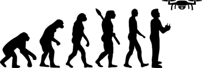
So, on with the evolution. PPK is similar to RTK, in that it uses multiple constellation dual-frequency GNSS carrier phase data from clocks on satellites, applying ionospheric modeling to determine cycle ambiguity resolution and relative range data between a base and rover. Heavy duty tech! Essentially a complex way to very accurately measure the vector from the base station to the drone, many times pers second. So, you need a base station (with a known coordinate) or data from a Continually Operating Reference Station (CORS). With PPK you can go a lot further from your base than RTK, but it is still typically best under 30km (20 miles).
Which brings us to the next ‘species’ in our evolution: Make It Accurate (MIA). MIA will make your drone rover data accurate, anywhere in the world, without any base station data. MIA is based on PPP (precise point positioning) technology that applies precise clock and orbit corrections to raw carrier phase GNSS data. Knowing exactly where each satellite was, and their precise clock errors, the stand-alone position of the drone can be determined to 5cm accuracy. This result is further improved in many countries by merging data from ground stations in the region, to get to 2-3cm absolute accuracy. No base station or CORS inputs – just fly your drone, anywhere. Multiple sites, remote areas, long corridors… anywhere. It’s accurate.
Again, we can’t stress enough, no matter what system you use, have your checks in place, measure how accurate you are.
Rob Klau, Director of Klau Geomatics, manufacturer of KlauPPK and MakeItAccurate.com. Rob is a career geodetic/exploration/GNSS surveyor registered with the Surveying and Spatial Science Institute, Asia Pacific.
