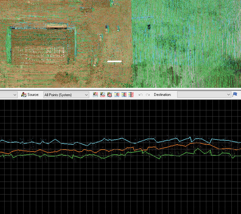
Figure 1: Vertical alignment assessment.
We have built dozens of True View 410 3D imaging Systems (3DiS) for sUAS over the past several months. With each unit, we do three manufacturing flight tests: an initial magnetic calibration flight, a full laser scanner/camera system calibration and finally a quality assessment flight. I wish I could convey how many hours and days we have spent perfecting our calibration processing and improving accuracy assessment: it has been an education!
We are building a repertoire of procedures that I feel are applicable to any drone camera/laser scanner system. The general areas of consideration are:
- Swath to swath alignment
- Local accuracy
- Network accuracy
Swath to swath misalignment is nearly always assessed as vertical separation between overlapping flight lines. For small area projects where the data were collected in a relatively short time span (e.g. several drone flights), these misalignments are dominated by two issues; a low quality inertial measurement unit (IMU) and/or mischaracterization of the angles between the IMU and the laser scanner (so-called “bore sight” angles). If you have a low accuracy IMU, you are out of luck (that money you saved on the front end will cause you no end of grief over the lifetime of the system!). Bore sight misalignment is easily corrected via a system calibration process. This can be tedious for multibeam systems such as Velodyne and Quanergy scanners since the process must be repeated for each beam. If you find that your system is not holding bore sight calibration from flight to flight, you may have a mechanical problem with the scanner. For example, I have seen some setups where the IMU was physically separated from the laser scanner by flexible carbon fiber rods: this design will never produce good data.
Figure 1 illustrates an area of three overlapping flight lines with significant misalignment. The grid spacing in the profile view is 10 cm. Note that the assessment tool is GeoCue’s LP360 (True View Evo), using a line drape function that colorizes the drape lines by flight line. A line separation of about 20 cm is evident in the figure. While this appears as a vertical separation, it is caused by bore sight misalignment.
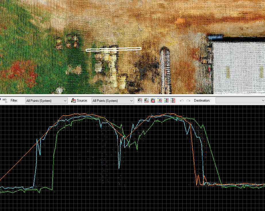
Figure 2: Horizontal Alignment.
A second assessment that is critical to judging the consistency of lidar data is horizontal alignment. Figure 2 is a cross section of several round hay bales, again with the profile shown as swath separated draped lines. Note the significant horizontal separation of about 40 cm between the cyan and green swath (most evident in the left side of the profile). This is again a result of bore sight angle misalignment. Note also the relatively good vertical alignment exhibited in the right side of the profile. This points out that just because you have good vertical alignment, don’t expect this to carry over to horizontal.
Scale issues are more common in photogrammetric projects where an incorrect focal length is being held during processing. Scale can be assessed with either standard check points (assuming you have a method such as RTK to measure the points) or by using objects of known length in the scene (scale bars).
Finally, Network Accuracy is an assessment of how well the data set, now internally consistent, match a particular datum. This assessment is invariably conducted using check points that have been “surveyed in” using some technique such as RTK. In an ideal world, you would always do this assessment using check points that are independent of the reference being used by the aerial platform. For example, use one base station for post-processing of the airborne sensor’s positioning data and a second base station for surveying in the check points. Using this technique will uncover common blunders such as an incorrect base station height.
Not well developed at this time are standard techniques for assessing the network horizontal accuracy of lidar point clouds. For our own True View 3DiS, we use the imagery since it is locked, via body frame calibration, to the lidar data. In laser scanners without firmly locked photogrammetric quality cameras, new techniques such as the generation of synthetic check points from linear feature intersections are needed. We will be looking at developing these tools this year.
The conclusion here is to not be satisfied with only a network vertical accuracy report for your lidar data. This will only reveal horizontal issues if the check points were placed on sloped surfaces. You really need to take a deeper dive. In other words, don’t keep it between the ditches: look in the ditches!