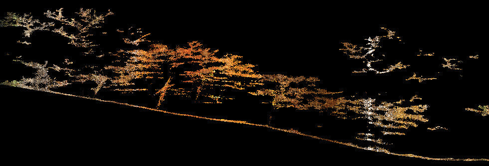
Figure 1: LIDAR data colorized from an ortho.
I really think it is time, particularly in the small unmanned aerial systems (sUAS) mapping arena, to make high accuracy colorized 3D point clouds the base data standard. I coined the term “3D imaging System” (3DiS) for the systems that can create these data. With that said, what exactly is a 3DiS?
The first part of 3DiS is the 3-Dimensional (3D) bit. A 3DiS must be capable of directly sensing a surface. For now, this means that 3DiS are limited to active sensors: LIDAR, Sonar, Radar. Photogrammetry cannot be the 3D part of a 3DiS because it does not provide accurate range data for many scene types such as vegetated areas, wires, thin vertical objects, poorly lit objects, objects free of texture and so forth. For sUAS mapping, this means the sensor must contain a LIDAR.
The “I” part of a 3DiS is imagery. These data are used to “paint” the 3D points obtained from the active sensor part of the 3DiS (again, LIDAR for a drone mapping system). Most commonly, the imagery will be supplied by visible spectrum (“Red-Green-Blue”, RGB) cameras flown concurrently with the 3D sensor. However, it could certainly be infrared, multispectral and so forth depending on the requirements of downstream applications. The imagery must be concurrently acquired with the 3D data. This rule is in place because objects move. Consider a construction site with a lot of mobile equipment. The 3D data cannot be properly painted with imagery if objects moved between the time of acquisition of the 3D data and the imagery. Thus a first pass with a LIDAR and a second pass with a camera will not quality as a 3DiS.
The third requirement is that the 3D data must be “painted” with the true “color” of the object at that point (here we use color loosely—it could be infrared, multispectral and so forth). For example, if a green tree leaf is directly over a yellow paint strip on a road (meaning both points share the same planimetric coordinates), the 3D point corresponding to the leaf must be painted green and the 3D point on the road must be colored yellow. This is a major point (pun intended) for a 3DiS. It means the painting of the 3D points must use the original image data for “colorization”, not a derived product such as an orthophoto. While the painting of points can occur in real time on the sensor itself, it more typically occurs in post-processing software. Thus the “S” in a 3DiS can be interpreted as “Sensor” or “System.”
This final requirement of painting the 3D point with the correct image pixel adds a high level of complexity to a 3DiS. The cameras must be tied to the Position and Orientation System and fully calibrated. Post-processing software must implement algorithms that can effectively ray trace from each 3D point to the appropriate pixel in the “best” source image. In our example above, the image acquired when the sensor is directly over the tree/paint strip would be the correct one for painting the leaf whereas a non-nadir image that is “peeking” beneath the tree will have to be selected for the road strip 3D point. It’s complicated!
Most providers of drone LIDAR that integrates one or more cameras do not implement 3DiS. Instead they have a workflow that creates a digital orthophoto and then recommend a third-party software (Global Mapper, for example) to simply color the LIDAR using a digital orthophoto. If you think about it, this cannot possibly be correct. An orthophoto contains a single color pixel for a particular X, Y location in the scene. If I had a pipe on the ground under a lattice structure under a tree, I would have three points from the LIDAR but only one point from an ortho (most likely the tree point). All three points would be colored the same. This problem is very nicely illustrated in Figure 1. These data were produced from a very high-end drone LIDAR/camera system (list price over US $200,000). We can clearly see the vertical bands of color; the signature of the “quick and dirty approach” of colorization from an orthophoto. Not only are these data wrong but downstream processing that relies on correct colorizing will fail.
It should be evident that there is a very big difference between “colorizing” LIDAR data and a true 3DiS data set. If you plan to invest in an sUAS LIDAR system, make certain the scheme is compliant with the requirements of 3DiS. Also be aware that a 3DiS cannot be fully achieved in hardware or software alone; it takes a careful system design of both. Thus if you are acquiring a sensor but part of the workflow software is from a third party, you are probably not getting a true 3DiS. A good example of a well-engineered 3DiS is GeoCue’s True View 410!