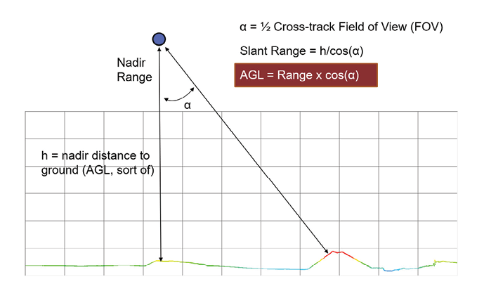
Figure 1: lidar Slant range.
Earlier this year, I gave a talk on interpreting specifications of UAV lidar systems. I promised a few folks that I would write a white paper on the topic and they took me up on the offer. To get started on this task (which I know will be a long time coming), I though I would devote this month’s column to considerations of UAV lidar systems that are capable of a very wide-angle field of view (FOV).
Editor’s note: A PDF of this article as it appeared in the magazine is available HERE.
Lidar scanners originally designed for mobile mapping or automotive applications (such as Velodyne) are now being adopted as airborne laser scanners for UAV deployment. These scanners often use either a set of fixed laser diodes on a rotating spindle or a single laser steered by a rotating mirror. As such, they offer a 360° or near 360° FOV. This is fine, though much of the data is wasted since the scanner is imaging the bottom of the UAV and/or the sky. The problem comes in when you examine the specifications some of the scanner integration companies are promoting. Let’s dive in to this a bit.
The useful range of a lidar system is the distance from the sensor to the point where the beam intersects the object of interest (typically the ground). This is not the flying height of the UAV (Above Ground Level, AGL) but rather the slant range to the ground (Figure 1).
Now the problem is several lidar integrators indicate that you can increase swath width by simply lowering AGL. For example, suppose you have a lidar with a specified range of 100 m. If you let the off-nadir angle increase to 65° and fly at an AGL of 42 m, all should be good since the slant range at 65° will be 100 m. I have actually seen plots in lidar integrator manuals that show swath width versus AGL based on this sort of flawed logic.
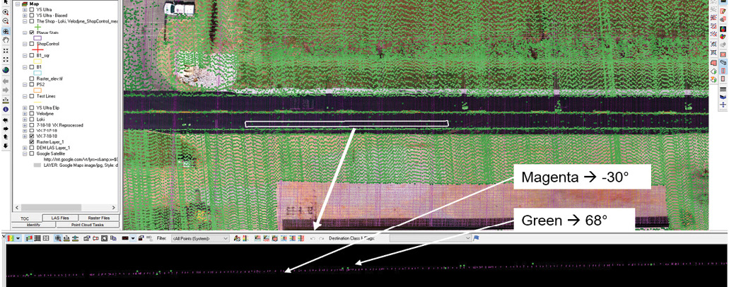
Figure 2: Effect of beam slant on receiver sensitivity.
The flaw in this thinking is the fact that a laser beam diverges as it travels out from the emitter. For example, the spot size of a Riegl miniVUX at 100 m is 16 cm (it is not really round but that does not matter for this discussion). If the beam makes an angle with respect to the ground, the spot elongates into an oval with the major axis in line with the beam. This phenomenon reduces the beam energy per unit area (since the area is increased), significantly impacting the range detection sensitivity of the scanner.
The result of this phenomenon is illustrated in Figure 2. The rectangular white box positioned over the road in the plan view is sampling data for the profile view. Inside this rectangle, points in green are at about 68° off nadir whereas those in magenta are about 30° off nadir.
Notice several problems with these data. First of all, we are getting very few returns from the 68° data (green) except over paint stripes. Secondly, notice that these points are at the wrong elevation. They are higher than the road surface (I measured this at an average value of 8 cm).
The conclusion here is to be wary of system integrator specifications on lidar performance. Just because you can hip shoot points at 70° off nadir does not mean you should! In fact, my back of the envelope recommendation is to limit the useable portion of a swath to no more than 45° off-nadir.
As mentioned, I intend (one of these days!) to create a white paper on interpreting specifications for UAV lidar systems. Perhaps I can even persuade Stewart to publish it in this magazine as a proper article!