
Figure 1: The exposure points after the data has been collected.
Earlier, a two-part paper was published on the “Evolution of the Point Cloud”, in which data from different UAS platforms was evaluated. Six different UAS data collections were performed with camera and LiDAR sensor at two different altitudes. During the course of collection, the authors learned valuable lessons on UAS-based data collection and processing. In this paper we will discuss the “lessons learned” from this UAS project that has helped us in developing “Best Practices for UAS Operations”
Editor’s note: A PDF of this article as it appeared in the magazine is available HERE.
The unmanned aerial systems (UAS) provide a new alternative approach to traditional aerial acquisition or ground-based surveys. Picking up where traditional methods of acquisition are limited either in ability or expense, UAS promise to unlock new opportunities for users of geospatial information. With UAS, one can create typical photogrammetric products at resolutions that are not available from conventional systems, and hybrid datasets from pixel-based point clouds, with per-square-meter densities not achievable from LiDAR, will drive the demand for new products.
Any UAS project will involve lot of planning and involves:
- FAA Regulations and insurance requirements
- Project Planning
- Flight Planning
- Flight Operations (Pre and Post)
- Ground Control
- Image processing
The FAA rules governing sUAS (small Unmanned Aircraft Systems) operations are published under 14 CFR 107, otherwise known as “Part 107.” Part 107 includes requirements for all remotely piloted aircraft under 55lbs that are operated for any purpose other than recreational flying. Survey or other commercial operations are subject to the following requirements: faa.gov/uas/media/faa-uas-part107-flyer.pdf
The highlights of the requirements are that the pilot of the sUAS must hold a Remote Pilot Certificate issued by the FAA. The aircraft must NOT be flown beyond unaided visual line of sight, NOT be flown over 400ft above the ground, NOT be flown over people, and NOT flown in certain airspace. These rules can provide challenges for certain operations, and the FAA can issue certificates of waiver or authorization to bypass rules for special limited operations if risks are mitigated to acceptable levels. The RPIC (Remote Pilot In Command) is ultimately responsible for his/her flights.
It is important to remember that UAS aircraft must be operated under the FAA UAS guidelines. The issues that needs to be addressed at this stage are the
- Remote Pilot Certificate validity and any insurance coverage to the pilots
- Operational and safety requirements for all operational aircraft and at the project site
- State licensing laws that define the practice of professional engineering or surveying
Certificated remote pilots will understand aviation, air space regulations, navigational charts, aviation weather etc. The pilot may also need to go through the UAS manufacturer’s training and have sufficient practice time on the aircraft of choice to ensure competent and safe operations. To conduct survey operations, the pilot also should have some exposure to aerial photogrammetry and LiDAR concepts.
It would be advisable to collect/collate all GIS layers that will play a role in the UAS data collection process
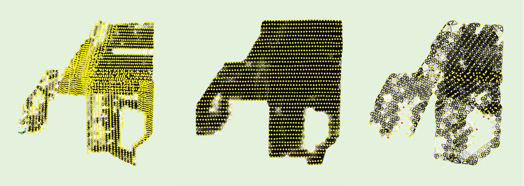
Figure 2: The cascading effect of missing flight lines with low overlap and poor quality of the blurry images has resulted in very few ties extracted.
Project Planning
In project planning, decisions have to be made on the following:
- Type of aircraft
- Sensor (Camera/LiDAR)
- Terrain Conditions
- Project area
- Expected deliverables with accuracy requirements
Although, many different types of UAS may be capable of performing a project, we need to always remember the cost advantage of the UAS mission over a manned mission for the same project. In some cases, the manned mission may be more cost effective compared to UAS mission or may provide other important project priorities (e.g., safety or accuracy) that the UAS cannot provide.
Aircraft types include fixed-wing, VTOL, or hybrid. Time of flight for each platform (aircraft plus power source) are different and shorter flight times “per charge” will require more flights to accomplish the same task. These factors can make the costs to increase.
The selection of sensor depends on the deliverables and the terrain condition. For example, if the terrain is highly vegetated and the product deliverable is 1ft contour, then LiDAR sensor may be a better choice.
Terrain Conditions play an important role in the creation of product and has been explained in detail in the earlier paper.
Project area: The advantage of UAS is that data can be collected quickly for a small area (around 300 acres). But there are many instances where we may need data collection for larger areas. We need to make an estimate on how many hours/days it is going to take to collect the data given the aircraft. The time taken to complete data collection will have direct impact on the cost.
Expected deliverables with accuracy requirements needs to be kept in mind in project planning
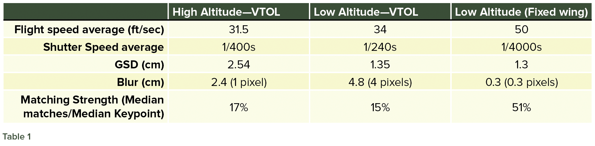
Table 1
Flight Planning
Like manned data capture, planning for a UAS based data collection is critical for the success of the project. Currently, many of the system manufacturers provide the flight planning software such as DJI GS pro, Pix4DCapture, DroneDeploy and Mission Planner.3rd party software is also often available for data capture.
The various parameters that need to be considered in UAS based data collection are
- Flight altitude
- Ground speed of the aircraft
- Forward and side overlap
- Ground Sample Distance (GSD)
- Shutter Speed
- frame capture rate
There is a common misconception that with a single-button press, a UAS pilot can operate the drone safely to capture all the images automatically. However, every project is unique. Many drones have 15-30 minute flight times, and it is necessary that flight plans for each lift required to cover an area are designed with sufficient forward and side overlap. Any underperformance in the overlap and side lap will lead to serious issues at the data processing stage and cause data voids in the point cloud.
Flight Operations (Pre and Post)
Best practices dictates that a checklist for the flight operation and the data capture teams are required and need to be reviewed carefully before each flight. The checklist will cover:
- Mission checklist
- Pre Flight Checklist
- Before Launch Checklist
- After landing Checklist
In any project, it is advisable, flight lines alternate directions and so contribute to a better estimation of frame centers when self-calibration is applied in the block adjustment. It is also advisable to ensure additional frames are collected at the end of each flight line. This helps ensure complete project coverage and high image quality results at the ends of flight lines.
As explained in our previous paper on “Evolution of the point cloud” published earlier, in order to take advantage of Structure from Motion (SfM) algorithms, the overlap should be 80% or above along the strips and 70% or above across the strips. This high overlap reduces image mismatches and increases the accuracy.
During the pre flight operations, care must be taken to insure the aircraft is properly calibrated. In order to avoid navigation and automatic stabilization problems, UAS often need an IMU and compass calibration on initial setup and when hardware changes are made. Operating very close to magnetically conductive structures or in magnetically disruptive environments may also cause challenges with the safe operation of UAS.
Post Flight: It is advisable that the pilot ensure that data is complete for the project area and that there are no missing data (e.g., frames, GPS) in the data collections. A variety of software are available to verify the data. These checks need to be completed before the pilot leaves the site to avoid refights at additional time and cost. Basically, the pilot should use the project boundary file, flight line file and the exposure points to ensure he has the complete coverage and that there are no gaps between the lifts. Figure 1 shows the exposure points after the data has been collected.
Ground Control
Like any mapping project, ground control plays an important role in defining the accuracy of the derived product. Best practice dictates that some check points are collected along with control points. The check points are not used to adjust the project, but are used as an independent accuracy check. The important components of check points and control points are:
- Size and shape of the targets
- The number and distribution of check and ground control points
The control points must be easily identifiable. With proper overlap between images, it is guaranteed that the same control will lie in multiple images. Selecting these points in multiple images will increase the accuracy of the control point selection during processing. Placing distinct identifiers at each control point may also reduce errors in downstream processing.
Based on our experience, we suggest that the image size of the control points is 6 to 10 pixels. With the current GNSS surveys using RTK mode, horizontal accuracies of 1 -2 cm and vertical accuracies of 3 cm can be achieved. ASPRS standards require the surveyed accuracy of the control and check points should be at least 3 times better than the required project accuracies. For example, if the vertical accuracy of the final product needs to be 9 cm, then the control accuracy should be better than 3 cm.
Image processing
Time spent preparing a solid flight plan with a quality control layout greatly facilitates the most expensive part of an UAS project: the data processing. However, any deficiencies in the flight planning and data collection “roll down hill”, that is, they impact data processing efficiencies, costs, and positional accuracy. The data collection should result with a minimum of 5 overlapping photos at any given point. More photos is always better. Less than 5 overlapping photos leads to difficulty in the aerotriangulation process.
Another important point that will play a role in the data processing is the shutter speed. It has been observed that the mismanaged exposure settings caused an average blur >0.5 pixel.
An analysis of the shutter speeds in the current project has resulted in the Table 1. As can be seen from the table, low altitude fixed wing data collection has resulted in smaller blur compared to VTOL. Although slower VTOL aircraft typically have fewer blur problems when flown slower, mismanaged exposure and shutter speed settings can cause problems. This table also explains the reason for getting below-par results with Inspire data collection.
Figure 2 shows the cascading effect of missing flight lines with low overlap and poor quality of the blurry images has resulted in very few ties extracted.
Conclusion
“Flying drones is easy. Mapping is hard.” Accurately assigning ground coordinates to billions of pixels taken from an inherently unstable platform flying overhead is really hard. Professionals understand this and have established “best practices” to ensure the quality and accuracy of the final mapping deliverables reliably and predictably meet the project specifications. Shortcuts are tempting but are often quite costly. As our profession communicates these important principles, the drone practitioners, the public and our clients benefit with world-class geospatial information.