Some years ago, we formed AirGon, our drone mapping subsidiary. Of course, being in the LIDAR and imagery business, we have always had a laser focus (pun intended here!) on high metric accuracy. For drone mapping with cameras, this means an on-board direct geopositioning system. For LIDAR mapping, orientation must also be known so the solution is onboard direct positioning and orientation system (POS). I thought it might be interesting to explore some of the options for direct geopositioning; we’ll leave POS for a future article.
At the end of 2016, we started investigating the possibility of doing serious mapping with very low end drone platforms such as the DJI Phantom 4 Pro and the Inspire 2 (with Zenmuse 4Xs cameras). We think these are the minimum drones (as compared to say the Phantom 3) because of some significant improvements to the cameras. The first is that the sensor size has been increased to 1”. This is really the minimum you should consider in a drone mapping camera. The second big improvement is the inclusion of a leaf global shutter. The rolling shutters of cameras primarily designed for video acquisition wreak havoc on photogrammetry solutions. With shutter speeds at or slower than 1/2000 s these new cameras employ a leaf shutter. We have calibrated these two cameras dozens of times and find fairly good stability.
The next issue brings us back to direct geopositioning. In designing Loki, our new direct geopositioning systems for DJIs, we had a lot to take in to consideration. For high accuracy drone mapping, we need an on-board survey grade direct geopositioning system to obtain a priori estimates for the camera positions. This is half (the X, Y, Z part) of the exterior orientation (EO) parameters, the other three being pitch, yaw and roll. It turns out that if you feed position only to most Structure from Motion algorithms (at least for aerial mapping), they will nearly uniquely optimize orientation. However, even with dense control, poor a priori position estimates do not converge to a unique EO solution. The message here is that for high accuracy work such as differential volumes and topographic contours, you need good a priori estimates of each camera position.
A critical issue with building a direct geopositioning system is synchronizing the camera trigger with the Global Navigation Satellite System (GNSS) receiver. GNSS receivers specifically designed for point location work include an event input. When a signal appears at the event pin, the time of the event is recorded. This allows recovery of the position associated with the event once the positional trajectory has been computed. With high end drone systems, this is pretty easy. One just builds an adapter to attach to the camera flash connection (hot shoe). With the camera set in flash mode, an event (called the Mid Exposure Pulse or MEP) comes over this signal wire each time an image is taken.
The low end DJI cameras do not include this MEP signal nor do they have a flash unit. After quite a bit of analysis, we devised a scheme wherein we listen to message traffic on the bus of the drone and discern trigger events (we have a patent pending on this and related schemes). Thus we have a MEP for these low-end systems.
There is a big debate in the drone community regarding the options in the design of a direct geopositioning system. Can it be accomplished with L1 only? Should it be real time or post-processed. Should I use a local base station?
Several years ago we designed a Post-Processed Kinematic (PPK) direct geopositioning system for our high end drone, the AV-900, using a GNSS engine from Septentrio B.V. of Belgium. We have done endless experiments with this direct geopositioning system, not only in customer support but in some 600+ mapping flights performed by our services division. We have some definite conclusions that have informed our new design.
First of all, a direct geopositioning system being used for high network accuracy must be a carrier phase system used in differential mode. I don’t think there is any debate about this in the community. Differential means that a reference station placed on a known location close to the rover (in our case the drone) is simultaneously collecting positional data. Since we know exactly (well, sort of!) the base location, we know the error the base GNSS receiver is computing. Since the error a short distance from the base is essentially the same (highly “correlated”) we can use this known error to correct the unknown error at the rover. This clever scheme is called “differential” GNSS.
Carrier phase detection (Figure 1) means the GNSS receiver is examining the radio signal on which the GNSS codes are superimposed (hence the name carrier) to refine distance. The navigation codes from GPS (the USA’s GNSS system), for example, are at a frequency of 1 MHz. Since light travels about 30 cm in 1 nanosecond, locking on to a navigation code will give me an accuracy of about 300m ! If I can get within 1% of aligning the signal chirps, I am still only accurate to about 3m. To circumvent this problem, GNSS scientists came up with a technique of looking at the carrier. For GPS L1, this signal is at a frequency of 1,574 MHz. This means one cycle of the carrier is about 19 cm long. If I can get to within 1% of this, the accuracy improves to about 2 mm! Thus carrier phase detection is required.
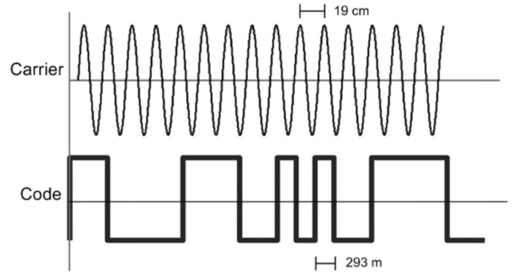
Figure 1: Carrier vs Code Detection
The other topic of some debate is the use of single frequency GNSS. GNSS navigation information is broadcast by the satellites on several different frequencies. For GPS the common bands are L1, L2 and L5. For GLONASS it is bands L1 and L2. As anyone who has purchased a GNSS receiver can testify, systems capable of receiving multiple bands simultaneously are considerably more expensive than single band receivers. This is why consumer grade GNSS receivers in smart phones and, for that matter, drone autopilots employ single band technology (L1 only receivers). In theory, a single band receiver operated in carrier phase differential mode could achieve the accuracy of a multiband receiver since the distance (actually time) discrimination schemes are identical. However, there are two problems with this. Carrier phase systems “lock” on to a cycle of the carrier. However, every cycle looks the same. Thus the receiver has to figure out how many integer cycles exist between it and the broadcasting satellite. This is termed ambiguity resolution. The second has to do with propagation delays in the atmosphere caused primarily by the ionospheric layer. This is illustrated in Figure 2. This error averages 5 m but, in “radio storms” can be much worse. Fortunately the delay in the ionosphere is inversely proportional to the carrier frequency squared. Since the delay is non-linear with respect to frequency, two different frequencies will be delayed by different amounts. Using algorithms based on the ratios of frequencies, a multiband GNSS receiver can virtually eliminate this random delay. A more insidious problem has to do with regaining lock when lost due to motion or noise. Again, using differencing algorithms, a multiband receiver can quickly recover lock whereas it can take minutes in a single band receiver. This effectively eliminates single band receivers for motion (kinematic) applications.
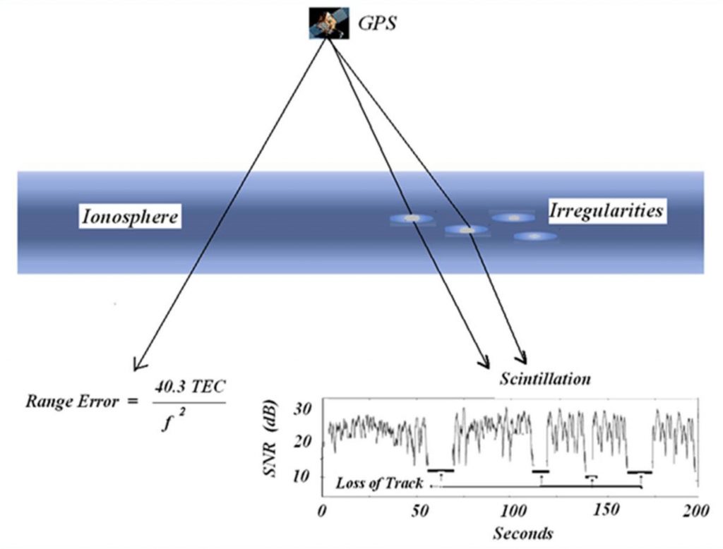
Figure 2: Ionospheric delay and loss of track
One final consideration is whether you need the completely resolved position as it is being collected (real time) or if you can wait until you are back at the office (post processed). Real time systems are a bit more complicated in that they must broadcast the error signal from the base to the rover via a radio link. Post processing systems require only that the raw data is recorded separately on the base and rover for later processing. The former is called RTK positioning whereas the latter is PPK positioning. In my opinion, PPK is the way to go with drones because it simplifies the system (no radio link) and does not suffer from loss of lock if something such as a stockpile blocks the radio link between the base and drone. An additional benefit is that PPK can be more accurate since it uses more accurate orbit data for the GNSS satellite locations.
The development of GNSS is arguably one of the most remarkable technological advances of the 20th century. It is absolutely remarkable that receiver systems have been miniaturized to the size of a deck of cards (with less weight!) that can discern position to several centimeters. With the advent of intelligent transportation systems, high accuracy differential GNSS will become ubiquitous. Hopefully this article helps you appreciate some of the tradeoffs in system design. Till next time, keep your phases on locked!